mename
Newbie level 4
Dear all,
I have faced a challenging problem that may be interesting for those who are in agile/precise control.
Realizing an actuation system for the following application, I appreciate any help/feedback:

My initial approach is:
1- Regardless of the motor type, I should setup a continuously running system (no start and stop several times a second!).
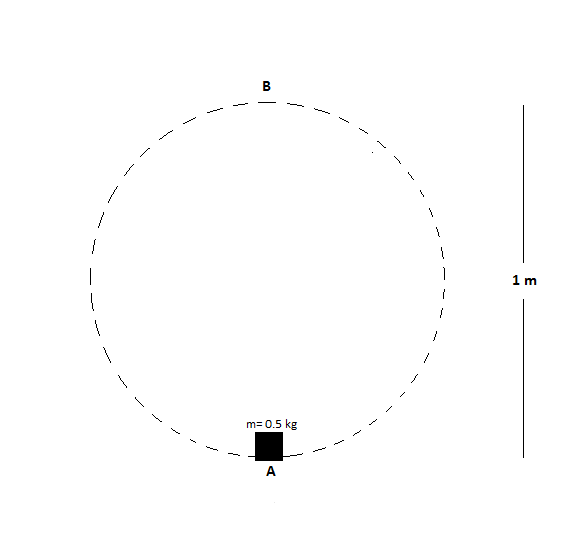
2- The actuator should move the load preferably on a circular path A-->B-->A-->B... in 0.2 sec and the load should be detached from the mover at point B by a detacher (electromagnetic detach/attach mechanism?) while the mover continues to run ensuring the constant running of the motor. 0.2 sec later, the attacher (electromagnetic detach/attach mechanism?) attaches the load to the mover while the mover takes the load to point A back again, and so on.
3- The rotational moving mechanism will render unnecessary the motor to change its rotation 2-3 times a second as it does if you go with a linear actuation style (back and forth).
4- The detachment and attachment mechanism, if it works, will render unnecessary the motor to stop for 0.2 sec while the load is at point A or B. An electronically controlled timer will energize the attach/detach mechanisms at A and B.
5- For the sake of energy efficiency, a single-phase ac motor may be chosen since it is required to power the system via single-phase 230V 16A switch.
6- Or, should I design an actuation system where I control the start-stop cycle of the motor for every 0.2 sec? If so, what type of control can I employ? A PID feedback control with position/velocity sensors? I suspect any ac motor, regardless of number of phase or use of VSD, will sustain such an agile movement for long time.
What do you think?
Regards,
Maxime
I have faced a challenging problem that may be interesting for those who are in agile/precise control.
Realizing an actuation system for the following application, I appreciate any help/feedback:
- A 0.5 kg load needs to be moved up and down between positions A and B. The (vertical) distance between A and B is 1 meter. The trajectory followed for the up and down motion is free.
- The load needs to be standing still in point A for 0.2 seconds, has 0.2 seconds to move up to point B, should be standing still in point B for 0.2 seconds and has 0.2 seconds to move down again to point A.
- Specific requirements: Energy efficiency is of utmost importance and the system has to be powered via a standard net switch (230V, 16A, 50-60Hz, single phase). This motion has to be continuously repeated.
My initial approach is:
1- Regardless of the motor type, I should setup a continuously running system (no start and stop several times a second!).
2- The actuator should move the load preferably on a circular path A-->B-->A-->B... in 0.2 sec and the load should be detached from the mover at point B by a detacher (electromagnetic detach/attach mechanism?) while the mover continues to run ensuring the constant running of the motor. 0.2 sec later, the attacher (electromagnetic detach/attach mechanism?) attaches the load to the mover while the mover takes the load to point A back again, and so on.
3- The rotational moving mechanism will render unnecessary the motor to change its rotation 2-3 times a second as it does if you go with a linear actuation style (back and forth).
4- The detachment and attachment mechanism, if it works, will render unnecessary the motor to stop for 0.2 sec while the load is at point A or B. An electronically controlled timer will energize the attach/detach mechanisms at A and B.
5- For the sake of energy efficiency, a single-phase ac motor may be chosen since it is required to power the system via single-phase 230V 16A switch.
6- Or, should I design an actuation system where I control the start-stop cycle of the motor for every 0.2 sec? If so, what type of control can I employ? A PID feedback control with position/velocity sensors? I suspect any ac motor, regardless of number of phase or use of VSD, will sustain such an agile movement for long time.
What do you think?
Regards,
Maxime