Continue to Site

Welcome to EDAboard.com

Welcome to our site! EDAboard.com is an international Electronics Discussion Forum focused on EDA software, circuits, schematics, books, theory, papers, asic, pld, 8051, DSP, Network, RF, Analog Design, PCB, Service Manuals... and a whole lot more! To participate you need to register. Registration is free. Click here to register now.

MASH ( SD modulator) power spectrum dc term

Status
Not open for further replies.

NikosTS

Advanced Member level 4
Joined
Jan 30, 2017
Messages
119
Helped
1
Reputation
2
Reaction score
2
Trophy points
18
Activity points
1,054
I am trying to plot the power spectrum of the quantization noise for a MASH topology(for frequency synthesizer) , but i have an offset of about 20 dB from the ideal curve.

On a last paper that i read , it was written that the desired power spectrum is given from the output of the SD modulator after removing the dc term.
What is the dc term that is mentioned? Is it the mean value of the sequence? ( in the case of frequency synthesizer, the fractional word)
Or just the term at frequency 0?

Thank you in advance,
Nikos
 

On a last paper that i read,
it was written that the desired power spectrum is given from the output of the SD modulator after removing the dc term.
What is the dc term that is mentioned?
Error due to resolution of data path.
 

Could you explain it a bit more extensively please?
Does it depend on the number of accumulator bits ( N ) or the fractional input?

Thank you
 

Well, as long as the initial condition is odd , fractional input should have no impact on the curve.
As far as the accumulator bits are concerned, they should add just a small difference on the magnitude. For any number of bits that i tried though, the difference between my curve and the ideal is a constant 20 dB difference.

Why does this constant difference exists? I am pretty sure my plot is correct ( spectrum analysis on Cadence Virtuoso)
 

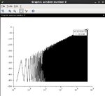
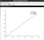
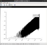
virtuoso_psd.jpgscilab_psd.jpgideal.jpg

OK so , the first image is the power spectrum as plotted from Cadence Virtuoso.
The second one is the power spectrum ( same configuration as in Virtuoso ), this time plotted in Scilab
The third one is the ideal curve, as it is written in the literature.
 

Use correct terminology.
OK so , the first image is the power spectrum as plotted from Cadence Virtuoso.
This plot is a result of dfft() of Cadence OCEAN function.

The second one is the power spectrum ( same configuration as in Virtuoso ), this time plotted in Scilab
It seems spectrum results are same between dfft() of Cadence OCEAN function and Scilab ?

What function do you apply in Scilab ?
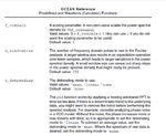
Even in Cadence OCEAN, two functions exist for evaluating Spectrum, dfft() and psd().

Do you use psd() or dfft() in Scilab ?

In MathWorks MATLAB, fft(), psd(), pwelch(), etc. exist.
https://www.designers-guide.org/Forum/YaBB.pl?num=1405235104/2#2

Definition of fft() is different between Keysight ADS PostProcessing and MathWorks MATLAB.

Definition of fft() is same between Keysight ADS PostProcessing and Cadence ADE PostProcessing.
https://www.designers-guide.org/Forum/YaBB.pl?num=1484736874/8#8

On a last paper that i read,
it was written that the desired power spectrum is given from the output of the SD modulator after removing the dc term.
What is the dc term that is mentioned?
There is no DC term in your plot.
On the other hand, DC term surely exist in my plot.
https://www.designers-guide.org/Forum/YaBB.pl?num=1361756819/3#3

but i have an offset of about 20 dB from the ideal curve.
Your issue has no relation to DC term.

Simply constant deviation between spectrum from time domain and Z-domain transfer function.

The third one is the ideal curve, as it is written in the literature.
Do you mean this is a result of Z-Domain Transfer function plot ?
Cadence OCEAN function, dfft() is not Z-domain tranfer function.
 
Last edited:

Thank you for your reply,

This plot is a result of dfft() of Cadence OCEAN function.

It seems spectrum results are same between dfft() of Cadence OCEAN function and Scilab ?

What function do you apply in Scilab ?
Even in Cadence OCEAN, two functions exist for evaluating Spectrum, dfft() and psd().

Do you use psd() or dfft() in Scilab ?

Yes, the plots from dfft() in Cadence OCEAN function and scilab are the same.
The plot from Scilab is also the result of using fft() ( and afterwards squaring the output).

If i use the equivalent of psd() function in Scilab ( it is named pspect) i get the following curve, which is way off ( going to positive dBs)
pspect.jpg

If , on the other hand, I use the psd() function in Cadence i get the following curve ( dBs dropped lower than the ideal curve, that is impossible i think).

cadence_psd.jpg


Do you mean this is a result of Z-Domain Transfer function plot ?

The ideal curve is simply the plot of the formula : Noise spectral density = (1/12*Sequence_length)* (1-z^-1)^6
(found in numerous papers, like Reduced Complexity MASH Delta-Sigma Modulator, Zhipeng Ye and Michael Peter Kennedy)

If i didn't make something clear, please tell me.
 

If i didn't make something clear, please tell me.
Still, you can not understand things correctly and also not understand correct terminologies.

Consider frequency bin width of result of dft() and definition of dft().

Surely consider what units are applied for y-axis of your plot each other.
In your setting, they are different each other.

fs ; Sampling Frequency
Nfft = 2^17
BinWidth=fs/Nfft

(1) db20( dft() ) - db10(BinWidth) gives dBV/Hz
(2) db10( psd() ) gives dBV/Hz
(3) db10( (1/12)/(fs/2)*abs((1-z^-1)^3)^2 ) which gives dBV/Hz

You can plot these three in Cadence ViVA.
https://www.designers-guide.org/Forum/YaBB.pl?num=1444923186/6#6
 
Last edited:
fs ; Sampling Frequency
Nfft = 2^17
BinWidth=fs/Nfft

For N=14 bits, the full sequence length is Ls=2^(N+1)=15. And i sample for 2 full Ls, that is 2^16 points.
My question is that , if i sample for let's say 16 full Ls, the binWidth according to your formula will be 2^(N+1) * 16= 2^19?
So according to this
Code:
(1) db20( dft() ) - db10(BinWidth) gives dBV/Hz

that means, there will be difference to the output spectrum if I sample more periods of the periodic signal?


(1) db20( dft() ) - db10(BinWidth) gives dBV/Hz
That one gives an output spectrum that peaks at around -60dB ( yet, as i mentioned above , it changes for longer sampling time )

(2) db10( psd() ) gives dBV/Hz
This one gives almost the same as above, so I guess it is ok.

(3) db10( (1/12)/(fs/2)*abs((1-z^-1)^3)^2 ) which gives dBV/Hz
According to the literature, (1-z^-1)^3)^2 expands to (2*sin(pi*f/fs))^6 right?
The thing that confuses me is the factor (1/12)/(fs/2). On almost every paper I came across, this factor is (1/12)/Ls.
If i plot your equation ( in SciLab ) , i get the peak at -80 dB ( big enough difference from the measured data ).
If i plot my variation ( that is substituting fs/2 with Ls ), i get the peak at -40 dB (still 20 dB difference from measured data ).

Thank you for your time
 

Tottally, I can not understand what you want to mean at all.
Before posting, study basic mathematic.

For N=14 bits, the full sequence length is Ls=2^(N+1)=15.
I can not understand what you want to mean at all.

Full sequence length is 2^Nbit - 1 = 16383, Nbit=14

I And i sample for 2 full Ls, that is 2^16 points.
I can not understand what you want to mean at all.

There is no direct constraint between Nfft and Nbit.

Show me the followings.
fs ; Sampling Frequency
Tstart ; argument for dft()
Tstop ; argument for dft()
Nfft ; argument for dft()

Nfft have to be (Tstop-Tstart)*fs.
delta_f = 1/(Tstop-Tstart)

My question is that , if i sample for let's say 16 full Ls, the binWidth according to your formula will be 2^(N+1) * 16= 2^19?
I can not understand what you want to mean at all.

that means, there will be difference to the output spectrum if I sample more periods of the periodic signal?
I can not understand what you want to mean at all.

Normalized Spectrum(dBV/Hz) is not so dependent on sample periods as far as delta_f is relative small.

Show me results of following and setting.
(1) db20( dft() ) - db10(BinWidth)
(2) db10( psd() )

According to the literature, (1-z^-1)^3)^2 expands to (2*sin(pi*f/fs))^6 right?
Maybe right.

The thing that confuses me is the factor (1/12)/(fs/2).
On almost every paper I came across, this factor is (1/12)/Ls.
Rather I don't see such expression.
I think your expression is normalized as unitless, so its denominator is not Hz.
Surely read your every paper.

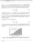
Attached is a extract from very famous book.
https://www.amazon.com/Understandin...GIC_1_1?s=books&ie=UTF8&qid=1484826787&sr=1-1

Also see Eq.(23) the following.
https://www.adv-radio-sci.net/5/313/2007/ars-5-313-2007.pdf
This is phase noise PSD not delta_N PSD
See https://www.designers-guide.org/Forum/YaBB.pl?num=1444923186/6#6

If i plot your equation ( in SciLab ),
i get the peak at -80 dB ( big enough difference from the measured data ).
If i plot my variation ( that is substituting fs/2 with Ls ), i get the peak at -40 dB (still 20 dB difference from measured data).
Show me your results and fs.
 

Attachments

  • 170217-180318.png
    170217-180318.png
    81.6 KB · Views: 147
Last edited:

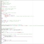
OK, as it seems i have trouble explaining what i mean, so i am attaching the script that i run for the plots ( i have added as many comments as necessary i think, but if you need more info on any line of the code tell me.)
The script is written in Scilab ( the syntax is almost identical to Matlab, so you won't have trouble understanding it ).
script1.jpg
scripts2.jpg

The plots generated are the following.
plots.jpg
 

OK, as it seems i have trouble explaining what i mean
Simply you can not understand basic mathematic especially fft.

Surely read your every paper.

Show me informations I requested in #12.

You don't show at all.

Show me the followings.
fs ; Sampling Frequency
Tstart ; argument for dft()
Tstop ; argument for dft()
Nfft ; argument for dft()
........................................
Show me results of following and setting.
(1) db20( dft() ) - db10(BinWidth)
(2) db10( psd() )
These are for Cadence ViVA using time-domain data.

Show me your results and fs.
This is for Plot using frequency-domain data in Scilab.
 
Last edited:

fs=1GHz
Nfft=65536=2^16
Tstart=2.125002nsec
Tstop=Tstart+2*32768/fs=Tstart+Nfft/fs

BinWidth=fs/Nfft
db10(BinWidth)=41.8dB


(1) db20( dft() ) - db10(BinWidth) gives -64.2481dB at 493.713MHz
(2) db10( psd() ) gives -58.578dB at 473.419MHz

Show me (3) db10( (1/12)/(fs/2)*abs((1-z^-1)^3)^2 )

Ok, for all cases N=14 and input 2037 as before.
.................................................
"Cout" is the output carry sequence with range [-3,4] from the 3rd order SD modulator
Are your outputs in Spectre truely [-3,4] ?
I think they are 2^Nbit*[-3,4].
 
Last edited:

Show me (3) db10( (1/12)/(fs/2)*abs((1-z^-1)^3)^2 )

I wasn't sure how to plot it in Virtuoso , so i plotted this one in Scilab.
ideal.jpg

Are your outputs in Spectre truely [-3,4] ?
I think they are 2^Nbit*[-3,4]

Yes they are in the range [-3,4]
 

timedomain.jpg

That is a small segment of the waveform
 

>> fs=1e6;
>> f=fs/2=0.5e6;
>> Se=(1/12)/(fs/2);
>> Sq=Se*(2*sin(pi*f/fs))^6;
>> 10*log10(Sq)
ans = -49.7197

See result of order=3 of the following.
https://www.designers-guide.org/Forum/Attachments/hoge_001.jpg

Here order=3, fs=1MHz
You can see -50dB/Hz Spectrum at f=fs/2=0.5MHz.

My results from Cadence Spectre Transient Analysis using Verilog-A DSM Model is very close to Sq.

You set fs=1e9, so Se is fairy small.
Sq=-79.7dB/Hz at f=fs/2 is reasonable.

Raw_Spectrum is a result of db20( dft() ) with hanning window.
See Appendix-A of the followings.
https://www.amazon.com/Understandin...GIC_1_1?s=books&ie=UTF8&qid=1484826787&sr=1-1

Smoothed_Spectrum is a db10( circ_smooth( mag(inv_db20(Raw_Spectrum))**2, 16 ) ).
I ported "circ_smooth()" of delta-sigma toolbox of MATLAB to Cadence ADE as Skill function.
https://jp.mathworks.com/matlabcent...ta-sigma-toolbox/content/delsig/circ_smooth.m

Now you apply window size=Nfft.
Try to reduce window size of psd(), such as Nfft/2, Nfft/4, Nfft/8, .....

I am trying to plot the power spectrum of the quantization noise for a MASH topology(for frequency synthesizer)
Why do you use fs=1GHz ?

I can not believe such high frequency clock for Delta-Sigma-Fractional-N Frequency Synthesizer.

Assume fvco=10GHz.
fs=1GHz means average divide-ratio is around 10.

3rd-Order-DSM perturb divide-ratio from 10-3 to 10+4.
Generally unless average divide-ratio is enough large compared to delta_N range, e.g. [-3, 4], DSM-PLL can not work.
 

Attachments

  • 170218-013507.png
    170218-013507.png
    97.9 KB · Views: 136
Last edited:

Status
Not open for further replies.

Part and Inventory Search

Welcome to EDABoard.com

Sponsor

Back
Top