piper
Newbie level 2
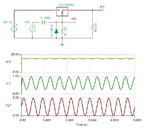
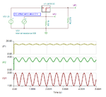
i have to design a test fixture for measuring PSRR - power supply rejection ratio - for a sample-and-hold (track and hold) amplifier.
The test procedure says to add a 2.4 KHz sine wave to the Vcc which is 15 volts in this case and measure the signal on the output. The expected PSRR is -30 dB min. I thought of using a transformer to couple the ac onto the positive power supply and adjust the positive voltage to get +15 V, 55 mA at the VCC input of the IC. But I am confounded by the specifications of audio transformers to accomplish this. I know I want a 1:1 but not 600 ohm impedance. I understand I should not put decoupling capacitors on the power supply inputs of the device and that I probably want a "swamping capacitor" on the voltage terminals. But what I don't know is what type of transformer and what parameters I should be looking for.
Note: I don't want to wind my own transformer - there are plenty on the market.
Any suggestions welcomed. I can't measure the IC yet as it hasn't been produced yet. It is an old design of an obsolete part and the design engineers are long gone.
Thanks