Enzy
Advanced Member level 1
I wanted to build a circuit that can use 24vdc and converter to Ac @800v at about 60khz any wave form is acceptable, I was wonderin if anyone knew of any working circuits I could try out in a similar range.
Follow along with the video below to see how to install our site as a web app on your home screen.
Note: This feature may not be available in some browsers.
Hi,
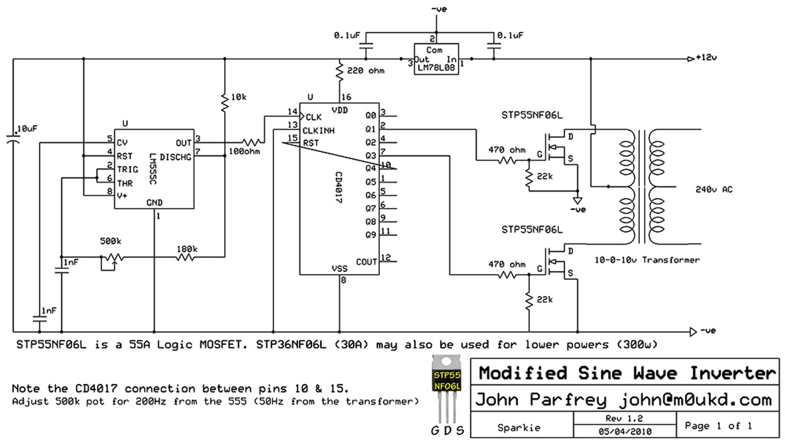
Turn ON and turn OFF of the Mosfets will be slow, causing a lot of switching losses.
The transformer is 50% OFF, this additionally reduces efficiency. (25% OFF, 25% positive, 25% OFF, 25% negative). I don´t know if this is what you need.
VDD of the 4017 urgently needs a capacitor to GND.
I´d say this is a "minimal effort" circuit. Don´t expect much.
Klaus
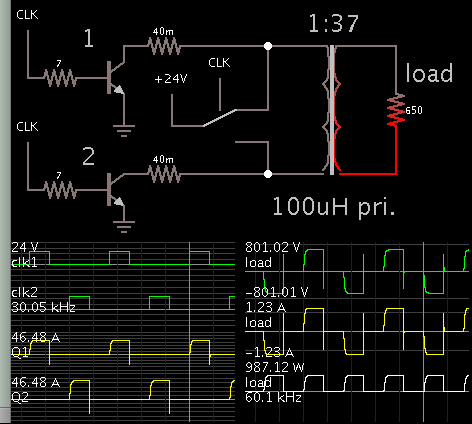
Hello BradtheRad, want to ask, what software did you use in setting up that circuit ?
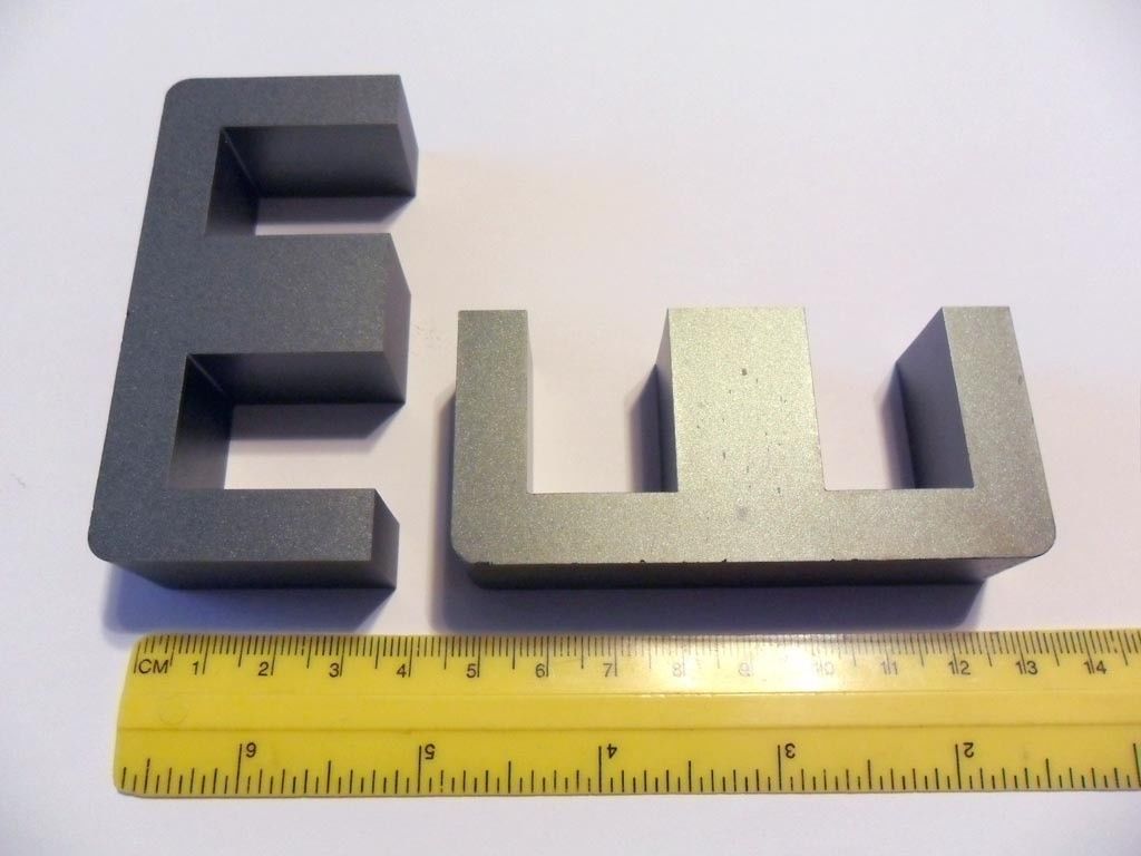
First i made a mistake above. The last
sec
pri
sec
pri
should have been.
sec
pri
pri
sec
With that said, if you use litz wire you can do a
sec
pri-pri
sec
and by dumb luck, there is a 20 amp litz wire on Ebay now.
"Type 2 Litz wire, 660/38 AWG, 30 feet, Equivalent to AWG #10 wire"
The primary layer would have both primary windings wound side by side. Because they are low voltage this will not be an insulation problem.
So secondary and 3 wraps of Mylar tape, both primary windings and 3 wraps of Mylar tape, then last secondary and at least 2 wraps of Mylar tape on exterior. Do not forget the Sleeving/Shrink Tube on every wire exiting the transformer, very important for the high voltages present.
Also i was optimistic in winding length. Before you start know how much room you have. Buying a bobbing will be almost impossible. You will have to make one by winding paper up into a tube and gluing some ends on. When you are finished then measure how much room you have left and how the wire will fit.
Do not give up your 3mm margins minimum on each end. This is vital to safety. Your Mylar tape will extend into the margins and touch the ends of the bobbin. The margin is designed to give a clearance between each layer to prevent the secondarys from shorting to the primarys.