Continue to Site

Welcome to EDAboard.com

Welcome to our site! EDAboard.com is an international Electronics Discussion Forum focused on EDA software, circuits, schematics, books, theory, papers, asic, pld, 8051, DSP, Network, RF, Analog Design, PCB, Service Manuals... and a whole lot more! To participate you need to register. Registration is free. Click here to register now.

150 to 250V 1A Generator Circuit

Status
Not open for further replies.

3BABY

Member level 5
Joined
Jan 14, 2011
Messages
91
Helped
0
Reputation
0
Reaction score
0
Trophy points
1,286
Location
New Zealand
Activity points
2,252
Hi Guys,

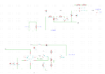
Im having a bit of trouble with a circuit. Please see schematic below. the top portion is a Capacitor Discharge Ignition circuit using a SCR, this is triggered by a microcontroller (not in schematic), the second portion is a 150-250V DC generator using a Step-Up DC-DC Controller (using the MAX1771) which was basically the same circuit as this Nixie tube HV generatoe

The Problem i have is i dont think the MAX1771 generator circuit can supply enough energy to the charge the capacitor, as far as im aware (after building the circuit) the 1uF capacitor would require approximately 1A at around 200V for 350uS. At the moment when i power on the system with a test program generating periodic 1mS (ON --> trigger SCR) pulses and 50mS apart this causes (Using OPTION 2 on the schematic, a direct connection from HV generator to CDI circuit (please see schematic)) the inductor of the MAX1771 circuit to breakdown and i end up with a fried inductor. If i use OPTION 1, a resistor in between the HV generator and the CDI circuit the resistor ends up getting fried.


So my question is: if i need to think about a different design for my high voltage generator, a design that can deliver approx 1A@ 200V DC in 350uS can anyone suggest a circuit? whether is be a DC-boost type or even a transformer.

Before anyone points out, yes most engines using CDI ignition have a HV generator coil for this purpose, i would not like to use this approach as this relies on engine RPM to generate a decent spark. i would like a stand alone HV generator to deliver sufficient spark energy at any RPM.

Periodic 1mS pulse to trigger SCR:
3.png

Schematic of current System:
5.png

Any Help would be much appreciated!
 

Hi,

Your step up circuit seems to be correct, but there is only a small output capacitor. 100nF. Is the value correct?

But I don't understand the ignition circuit, how it should work with the 1uF in series to the ingition coil.
Is the circuit correct?
Could you give a little description?

Klaus
 

Hi,

Your step up circuit seems to be correct, but there is only a small output capacitor. 100nF. Is the value correct?

But I don't understand the ignition circuit, how it should work with the 1uF in series to the ingition coil.
Is the circuit correct?
Could you give a little description?

Klaus

Hi Klaus, yes according to the datasheet ref spec and with reference to the webpage where the step-up converter was used for the Nixie tubes the 100nF was incorporated, i did not put in another polarised HV capacitor on the HV side as i thought that C4/C5 would be the capacitors on this side of the circuit to be "charged".

w.r.t to the ignition circuit and CDI, initially the SCR is off and capacitors C4/C5 are charged via D2 and the primary winding of the coil, C4/C5 is then discharged when the SCR is triggered (BT151), allowing current to flow back through the ignition coil primary winding. The fast discharge through the ignition coil causes a high voltage to be developed across the coil secondary winding of the ignition coil to fire the spark plug.

do you think that charging a 1uF or 2uF capacitor to 150V would consume more energy than the DC converter can provide? it almost seems to me like there is some sort of direct short when i have the DC converter connected to the ignition circuit, the inductor is fried within 5 seconds using the 1mS pulse. The same results when i have a resistor in the 150V DC path, within 5 seconds the resistor is smoke.

any ideas?
 

Did you check if SCR is actually extinguished after discharge? An unsuitable ignition coil might prevent SCR turn-off. I also wonder if the freewheeling diode, which is uncommon in this circuit might cause problems.

A SCR staying on will kill the inductor by 12V short circuit because there's no means to disconnect the current.
 

Hi,

Ok. if your description is correct, then the ignition circuit doesn´t use back EMF to generate high voltage.
I don´t know whether this circuit and function is correct or not.

****
Charging power.
If I understand correctly, then the capacitor is charged every 50ms.
The energy stored in the capacitor is 0.5 x U x U x C = 0.011Ws
If you do this every 50ms this means 20 times per second. Then you need 0.22W average power.

current:
C = I x t / U; C = 1uF, t = 50ms, U = 150V. unknown: I
I = C x U / t = 1uF x 150V / 50ms = 3mA (average)

****
The SCR stays conductive as long as there is current flow in one direction.
If you use a resistive load then the SCR won´t release anymore, once it is triggered.
But wiht the inductive load... it may push the energy from the capacitanc into the inductance then the current may become zero.
For the circuit to work properly you need to release the gate trigger before new positive current can flow through the SCR.

--> try to lower the trigger pulse from 1ms to about 10us.

...Still unsure if I understand the function properly.

Klaus
 

I'm not sure that design will work at all.

As observed, 'option 2' will fry the components because the SCR will remain conductive once triggered and basically connect L1 across 12V through D2.
'Option 1' will limit the current, preventing damage but also reduce the available current to charge the capacitors although maybe not enough to be sure the SCR stops conducting.

I also can't see what all the components in the gate of the SCR do. It looks more like a transistor based circuit with an SCR substituted for an NPN BJT.

Brian.
 

try to lower the trigger pulse from 1ms to about 10us
I didn't notice the long trigger pulse. You are right, it's likely to keep the SCR on even with proper LC load.

It's quite easy to start with low pulse frequency (e.g. 1 Hz) and fail safe current limiting resistor. Provided the trigger pulse and circuit operation are O.K., you still have the problem that a defective ignition coil can prevent SCR from turning off. I think there should be a disconnect feature, at least a fuse.
 

Did you check if SCR is actually extinguished after discharge? An unsuitable ignition coil might prevent SCR turn-off. I also wonder if the freewheeling diode, which is uncommon in this circuit might cause problems.

A SCR staying on will kill the inductor by 12V short circuit because there's no means to disconnect the current.

FvM, yes this could well be the reason why, if i hold the Gate of the SCR at 0V there is no problem, if i bring it up to 5V (with 500ohm resistor) quickly and then back to 0V i can generate a spark, but then i have to be very quick to turn the power off to the system or the resistor (OPTION 1) starts smoking, it seems to me like the SCR does not turn "off" again.

Hi,

Ok. if your description is correct, then the ignition circuit doesn´t use back EMF to generate high voltage.
I don´t know whether this circuit and function is correct or not.

****
The SCR stays conductive as long as there is current flow in one direction.
If you use a resistive load then the SCR won´t release anymore, once it is triggered.
But wiht the inductive load... it may push the energy from the capacitanc into the inductance then the current may become zero.
For the circuit to work properly you need to release the gate trigger before new positive current can flow through the SCR.

--> try to lower the trigger pulse from 1ms to about 10us.

...Still unsure if I understand the function properly.

Klaus


Thanks for the Power calcuations Klaus, i will link you to the original article for the CDI ignition HERE. As Brian has pointed out below, what is all the trigger circuit conditioning, this is for the Trigger pulse that was usually from a coil that could generate [some] voltage (dependent on engine RPM). I must add i had built a prototype of the CDI circuit a few years ago (with the rigger circuit conditioning) and tested it with a transformer (connected to the mains at about 130V) and triggering it with the 5V microcontroller and the circuit worked fine. i cannot remember exactly what the pulse length to the SCR trigger was however. but it was most definitely only 5V.

i have tried 350nS positive 5V pulse to the SCR (on the current circuit) and this still results in inductor/Resistor melting.


I'm not sure that design will work at all.

As observed, 'option 2' will fry the components because the SCR will remain conductive once triggered and basically connect L1 across 12V through D2.
'Option 1' will limit the current, preventing damage but also reduce the available current to charge the capacitors although maybe not enough to be sure the SCR stops conducting.

I also can't see what all the components in the gate of the SCR do. It looks more like a transistor based circuit with an SCR substituted for an NPN BJT.

Brian.

Discussed above thanks Brian. As in the below diagram in the blue box, allot of the trigger circuit conditioning could be removed if the trigger was coming from a digital source and not a trigger coil.

6.png


I didn't notice the long trigger pulse. You are right, it's likely to keep the SCR on even with proper LC load.

It's quite easy to start with low pulse frequency (e.g. 1 Hz) and fail safe current limiting resistor. Provided the trigger pulse and circuit operation are O.K., you still have the problem that a defective ignition coil can prevent SCR from turning off. I think there should be a disconnect feature, at least a fuse.

FvM where in the circuit would you speficy the position of the fuse?


i think the most likley case is that the SCR is not being turned off. but im unsure why this would be the case. As mentioned before (a few years ago) i did have the CDI circuit working with the Transformer attached to the mains as the HV source, i would not like to take this as an example that the SCR in this circuit should behave the same simply because i have no circuit diagram for this circuit and it was so long ago i cannot remember the specifics, but this is the reason i have used this CDI circuit again in this current circuit, because i had proved that it did work (all those years ago). The difference now is that i have changed the High Voltage generator. Could this contribute to the SCR not turning off?

from Wiki the Modes of Operation for an SCR are:

1: Forward blocking mode (off state)
2: Forward conduction mode (on state)
3: Reverse blocking mode (off state)


Forward conduction mode:
SCR can be brought from blocking mode to conduction mode in two ways: either by increasing the voltage across anode to cathode beyond breakover voltage or by applying positive pulse at gate. Once SCR starts conducting, no more gate voltage is required to maintain it in the on state. There are two ways to turn it off: 1. Reduce the current through it below a minimum value called the holding current and 2. With the gate turned off, short out the anode and cathode momentarily with a push-button switch or transistor across the junction
 

A fuse dimensioned according to the expectable continuous current respectively the boost inductor rating should be placed in the 12 V supply. But it's only a last resort to avoid component damage.

The SCR behavior can be safely observed with single trigger pulses and a resistor limiting the charge current to a view mA. If the SCR doesn't turn-off although the trigger pulse is short, the ignition coil might be defective or there's a similar problem in the load circuit.
 

You need an oscilloscope to see what's actually going on.
 

Status
Not open for further replies.

Similar threads

Part and Inventory Search

Welcome to EDABoard.com

Sponsor

Back
Top