Continue to Site

Welcome to EDAboard.com

Welcome to our site! EDAboard.com is an international Electronics Discussion Forum focused on EDA software, circuits, schematics, books, theory, papers, asic, pld, 8051, DSP, Network, RF, Analog Design, PCB, Service Manuals... and a whole lot more! To participate you need to register. Registration is free. Click here to register now.

PC-817 not working properly

Status
Not open for further replies.

gauravkothari23

Advanced Member level 2
Joined
Mar 21, 2015
Messages
640
Helped
5
Reputation
10
Reaction score
4
Trophy points
1,298
Activity points
6,922
Hi all...
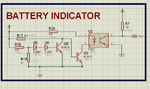
i am trying to build a small battery indicator (image attached), and trying to pull the micro controller pin high when the battery voltage goes low.
initial circuit was something different. instead of PC-817 anode and cathode, i was using a led. so when the battery voltage drops below 3.4v the LED lights up.
but now i have made a small alterations. i need to low battery indication to be sent to the controller by pulling the port pin high.
so i connected the pin 4 of PC817 to controller pin. but the thing is, the pin 4 of PC817 does not go low. it always stays high. when battery voltage is above 3.4v the output from pin 4 should be 0, but it stays high.
 

Attachments

  • bat ind.png
    bat ind.png
    33.3 KB · Views: 54

Hi,

The use of an optocoupler is useless when both sides are referenced to the same GND.
It's a waste of money and a waste of current.

A microcontroller usually has an ADC....if you use just two resistors as voltage divider and a capacitor then
* it saves money
* it saves current consumption
* it saves board space
* it is most flexible

Klaus
 

i am using AT89S52 microcontroller, which does not have any ADC. so for that reason i am using this type of circuits. and also i cant interface any External ADC IC's because of shortage of pins. i hardly have 2 to 3 pins left in my controller.
 

If you have 2 to 3 pins free then you can use I2C or SPI interface ADC chip.
 

ADC or not, as Klaus stated, the PC817 does nothing useful in that circuit.

Why not remove the PC817 and R20 then connect R7 directly to the collector of Q6?

Brian.
 

Hello.

Is it neccesary to isolate with the optocoupler? As I understood, the battery will supply the MCU and you want it to know when it's low.

There are a lot of solutions already made for that; many MCUs have a "low voltage sensor" flag you can use to do anything when that happens (put in stand-by, lower the circuit consumption by turning off circuit parts... saving energy, or to save data and turn off).

Then, if you don't know how to use that (or don't want to), you can use the ADC using the internal bandgap reference to measure the battery voltage.

And my least favourite one, if using the optocoupler, which would be the less accurate method (as you only know when it's low or not, but not an exact or aproximate value), you could aproach the proper inner LED breakdown voltage (read datasheet to know its value) and adding a zener or several diodes to get it turning off to a desired low voltage. That will turn the transistor on and will advert MCU that the battery is low.


EDIT:

Another solution, as I read you don't have ADC... use a transistor with a zener or some diodes in series with the base, and a resistor to the collector (output); if the battery is high, current flows through base and transistor is on. Otherwise, it won't happen, so when you get a "1" at the output (transistor off), the battery is low.

asddsaadsads.png

Like this
 
Last edited:

Status
Not open for further replies.

Similar threads

Part and Inventory Search

Welcome to EDABoard.com

Sponsor

Back
Top