Continue to Site

Welcome to EDAboard.com

Welcome to our site! EDAboard.com is an international Electronics Discussion Forum focused on EDA software, circuits, schematics, books, theory, papers, asic, pld, 8051, DSP, Network, RF, Analog Design, PCB, Service Manuals... and a whole lot more! To participate you need to register. Registration is free. Click here to register now.

[SOLVED] ATMega8A ADC Not Working

Status
Not open for further replies.

Okada

Banned
Joined
Jun 16, 2016
Messages
1,159
Helped
129
Reputation
252
Reaction score
129
Trophy points
63
Activity points
0
I am using ATMega8A to read ADC channel 0 and the code is working in Proteus but not on hardware (EasyAVR v7).

Here is the code. mikroC PRO AVR project and Proteus files attached.

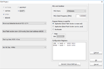
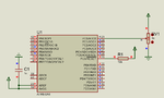
Images show circuit, project settings and fuses.

I tested LED blinking an all port pins and they work fine.

Code:
unsigned int adc_rd;

void main() {
    DDRB = 0xFF;               // set PORTB as output
    DDRC = 0x3E;               // set PORTC.0 as input for ADC
    DDRD = 0xFF;               // set PORTD as output
    
    PORTB = 0x00;
    PORTC = 0x00;
    PORTD = 0x00;
    
    REFS0_bit = 1;             // use AVCC as VRef
        
    while(1) {
      adc_rd = ADC_Read(0);    // get ADC value from 0th channel
      PORTB = adc_rd;          // display adc_rd[7..0]
      PORTD = (adc_rd >> 8);   // display adc_rd[9..8]
      Delay_ms(300);
    }
}
 

Attachments

  • ADC Measurement.rar
    39.7 KB · Views: 64
  • project settings.png
    project settings.png
    21 KB · Views: 99
  • Schematic.png
    Schematic.png
    32.3 KB · Views: 210

Are the ATMega8A's I am having fake ? I purchased them locally. Initially I think the PORT will be configured as output pins in a blank AVR. Right ? Before uploading code to new chip I connected 5V to ADC0 pin. Did this damage the ADC circuitry ? LED Blinking on all pins are working fine. I see a strange thing on my EasyAVR v7 development board.

With the configuration as mentioned in port #1, If I don't connect input to adc pin then I see LEDs randomly turning ON but If I input any voltage to adc pin then all Leds turn Off even though I vary the input voltage between 0 and 5V.

I bought 3 ATMega8A's, One from one vendor and two from another vendor. Till now used two of them and result is same.
 

Instead of using PORTD = (adc_rd >> 8);
use:
PORTD = (adc_rd >> 2);

ADC has 10-bit resolution. By shifting 8 bits, you will only be left with 2 bits.
 

ADC result is 10 bits. low byte 8 bits in displayed on PORTB Leds and I want the higher byte (2 bits) displayed on PORTD lower nibble.
 

AVCC is connected to VDD. I checked the continuity on the EasyAVR v7 board between AVCC and VDD pins.

Edit: I observed a very strange thing. This is the compiler generated assembly code. I don't see code related to ADC_Read() function.


Code ASM - [expand]
1
2
3
4
5
6
7
8
9
10
11
12
13
14
15
16
17
18
19
20
21
22
23
24
25
26
27
28
29
30
31
32
33
34
35
36
37
38
39
40
41
42
43
44
45
46
_main:
        LDI        R27, 255
        OUT        SPL+0, R27
        LDI        R27, 0
        OUT        SPL+1, R27
 
        LDI        R27, 255
        OUT        DDRB+0, R27
        LDI        R27, 62
        OUT        DDRC+0, R27
        LDI        R27, 255
        OUT        DDRD+0, R27
        LDI        R27, 0
        OUT        PORTB+0, R27
        LDI        R27, 0
        OUT        PORTC+0, R27
        LDI        R27, 0
        OUT        PORTD+0, R27
        IN         R27, REFS0_bit+0
        SBR        R27, BitMask(REFS0_bit+0)
        OUT        REFS0_bit+0, R27
L_main0:
        CLR        R2
        CALL       _ADC_Read+0
        STS        _adc_rd+0, R16
        STS        _adc_rd+1, R17
        OUT        PORTB+0, R16
        MOV        R16, R17
        LDI        R17, 0
        OUT        PORTD+0, R16
        LDI        R18, 7
        LDI        R17, 23
        LDI        R16, 107
L_main2:
        DEC        R16
        BRNE       L_main2
        DEC        R17
        BRNE       L_main2
        DEC        R18
        BRNE       L_main2
        NOP
        JMP        L_main0
L_end_main:
L__main_end_loop:
        JMP        L__main_end_loop
; end of _main

 
Last edited:

Hi,

Initially I think the PORT will be configured as output pins in a blank AVR. Right ?
Okada, again: read datasheets before posting trivial questions.
In chapter: "Register Description for I/O Ports"
It clearely says ddrx register initial value is 0x00.
0 means input.

Klaus
 
  • Like
Reactions: Okada

    Okada

    Points: 2
    Helpful Answer Positive Rating
PORTC.0 is the input port. DDRx is 0 means input pin. I have set DDRC to 0x3E; = 0b00111110. Isn't it right ? RST pin i sset as input pin also.


Also tried with CodeVisionAVR but the problem is same. i think it is a flaw of development board or the ATMega8A's are fake. I have to buy ATMega8A's from different source and try.


Code C - [expand]
1
2
3
4
5
6
7
8
9
10
11
12
13
14
15
16
17
18
19
20
21
22
23
24
25
26
27
28
29
30
31
32
33
34
35
36
37
38
39
40
41
42
43
44
45
46
47
48
49
50
51
52
53
54
55
56
57
58
59
60
61
62
63
64
65
66
67
68
69
70
71
72
73
74
75
76
77
78
79
80
81
82
83
84
85
86
87
88
89
90
91
92
93
94
95
96
97
98
99
100
101
102
103
104
105
106
107
108
109
110
111
112
113
114
115
116
117
118
119
120
121
122
123
124
125
126
127
128
129
130
131
132
133
134
135
136
137
138
139
140
141
142
143
144
145
146
147
148
149
150
151
152
153
154
/*******************************************************
This program was created by the CodeWizardAVR V3.28 
Automatic Program Generator
© Copyright 1998-2016 Pavel Haiduc, HP InfoTech s.r.l.
[url]http://www.hpinfotech.com[/url]
 
Project : ADC Example
Version : 1.0
Date    : 12/10/2016
Author  : Okada
Company : 
Comments: 
Example to read ADC input.
 
 
Chip type               : ATmega8A
Program type            : Application
AVR Core Clock frequency: 4.000000 MHz
Memory model            : Small
External RAM size       : 0
Data Stack size         : 256
*******************************************************/
 
#include <io.h>
 
#include <delay.h>
 
// Declare your global variables here
 
// Voltage Reference: AVCC pin
#define ADC_VREF_TYPE ((0<<REFS1) | (1<<REFS0) | (0<<ADLAR))
 
unsigned int adc_result = 0;
 
// Read the AD conversion result
unsigned int read_adc(unsigned char adc_input)
{
ADMUX=adc_input | ADC_VREF_TYPE;
// Delay needed for the stabilization of the ADC input voltage
delay_us(10);
// Start the AD conversion
ADCSRA|=(1<<ADSC);
// Wait for the AD conversion to complete
while ((ADCSRA & (1<<ADIF))==0);
ADCSRA|=(1<<ADIF);
return ADCW;
}
 
void main(void)
{
// Declare your local variables here
 
// Input/Output Ports initialization
// Port B initialization
// Function: Bit7=Out Bit6=Out Bit5=Out Bit4=Out Bit3=Out Bit2=Out Bit1=Out Bit0=Out 
DDRB=(1<<DDB7) | (1<<DDB6) | (1<<DDB5) | (1<<DDB4) | (1<<DDB3) | (1<<DDB2) | (1<<DDB1) | (1<<DDB0);
// State: Bit7=0 Bit6=0 Bit5=0 Bit4=0 Bit3=0 Bit2=0 Bit1=0 Bit0=0 
PORTB=(0<<PORTB7) | (0<<PORTB6) | (0<<PORTB5) | (0<<PORTB4) | (0<<PORTB3) | (0<<PORTB2) | (0<<PORTB1) | (0<<PORTB0);
 
// Port C initialization
// Function: Bit6=Out Bit5=Out Bit4=Out Bit3=Out Bit2=Out Bit1=Out Bit0=In 
DDRC=(0<<DDC6) | (0<<DDC5) | 0<<DDC4) | (0<<DDC3) | (0<<DDC2) | (0<<DDC1) | (0<<DDC0);
// State: Bit6=0 Bit5=0 Bit4=0 Bit3=0 Bit2=0 Bit1=0 Bit0=T 
PORTC=(0<<PORTC6) | (0<<PORTC5) | (0<<PORTC4) | (0<<PORTC3) | (0<<PORTC2) | (0<<PORTC1) | (0<<PORTC0);
 
// Port D initialization
// Function: Bit7=Out Bit6=Out Bit5=Out Bit4=Out Bit3=Out Bit2=Out Bit1=Out Bit0=Out 
DDRD=(1<<DDD7) | (1<<DDD6) | (1<<DDD5) | (1<<DDD4) | (1<<DDD3) | (1<<DDD2) | (1<<DDD1) | (1<<DDD0);
// State: Bit7=0 Bit6=0 Bit5=0 Bit4=0 Bit3=0 Bit2=0 Bit1=0 Bit0=0 
PORTD=(0<<PORTD7) | (0<<PORTD6) | (0<<PORTD5) | (0<<PORTD4) | (0<<PORTD3) | (0<<PORTD2) | (0<<PORTD1) | (0<<PORTD0);
 
// Timer/Counter 0 initialization
// Clock source: System Clock
// Clock value: Timer 0 Stopped
TCCR0=(0<<CS02) | (0<<CS01) | (0<<CS00);
TCNT0=0x00;
 
// Timer/Counter 1 initialization
// Clock source: System Clock
// Clock value: Timer1 Stopped
// Mode: Normal top=0xFFFF
// OC1A output: Disconnected
// OC1B output: Disconnected
// Noise Canceler: Off
// Input Capture on Falling Edge
// Timer1 Overflow Interrupt: Off
// Input Capture Interrupt: Off
// Compare A Match Interrupt: Off
// Compare B Match Interrupt: Off
TCCR1A=(0<<COM1A1) | (0<<COM1A0) | (0<<COM1B1) | (0<<COM1B0) | (0<<WGM11) | (0<<WGM10);
TCCR1B=(0<<ICNC1) | (0<<ICES1) | (0<<WGM13) | (0<<WGM12) | (0<<CS12) | (0<<CS11) | (0<<CS10);
TCNT1H=0x00;
TCNT1L=0x00;
ICR1H=0x00;
ICR1L=0x00;
OCR1AH=0x00;
OCR1AL=0x00;
OCR1BH=0x00;
OCR1BL=0x00;
 
// Timer/Counter 2 initialization
// Clock source: System Clock
// Clock value: Timer2 Stopped
// Mode: Normal top=0xFF
// OC2 output: Disconnected
ASSR=0<<AS2;
TCCR2=(0<<PWM2) | (0<<COM21) | (0<<COM20) | (0<<CTC2) | (0<<CS22) | (0<<CS21) | (0<<CS20);
TCNT2=0x00;
OCR2=0x00;
 
// Timer(s)/Counter(s) Interrupt(s) initialization
TIMSK=(0<<OCIE2) | (0<<TOIE2) | (0<<TICIE1) | (0<<OCIE1A) | (0<<OCIE1B) | (0<<TOIE1) | (0<<TOIE0);
 
// External Interrupt(s) initialization
// INT0: Off
// INT1: Off
MCUCR=(0<<ISC11) | (0<<ISC10) | (0<<ISC01) | (0<<ISC00);
 
// USART initialization
// USART disabled
UCSRB=(0<<RXCIE) | (0<<TXCIE) | (0<<UDRIE) | (0<<RXEN) | (0<<TXEN) | (0<<UCSZ2) | (0<<RXB8) | (0<<TXB8);
 
// Analog Comparator initialization
// Analog Comparator: Off
// The Analog Comparator's positive input is
// connected to the AIN0 pin
// The Analog Comparator's negative input is
// connected to the AIN1 pin
ACSR=(1<<ACD) | (0<<ACBG) | (0<<ACO) | (0<<ACI) | (0<<ACIE) | (0<<ACIC) | (0<<ACIS1) | (0<<ACIS0);
 
// ADC initialization
// ADC Clock frequency: 125.000 kHz
// ADC Voltage Reference: AVCC pin
ADMUX=ADC_VREF_TYPE;
ADCSRA=(1<<ADEN) | (0<<ADSC) | (0<<ADFR) | (0<<ADIF) | (0<<ADIE) | (1<<ADPS2) | (0<<ADPS1) | (1<<ADPS0);
SFIOR=(0<<ACME);
 
// SPI initialization
// SPI disabled
SPCR=(0<<SPIE) | (0<<SPE) | (0<<DORD) | (0<<MSTR) | (0<<CPOL) | (0<<CPHA) | (0<<SPR1) | (0<<SPR0);
 
// TWI initialization
// TWI disabled
TWCR=(0<<TWEA) | (0<<TWSTA) | (0<<TWSTO) | (0<<TWEN) | (0<<TWIE);
 
while (1)
      {
      // Place your code here
      adc_result = read_adc(0);
      PORTB = adc_result;
      PORTD = adc_result >> 8;
      delay_ms(300);
      }
}

 
Last edited:

code related to ADC_Read() function.
>CALL _ADC_Read+0

there is sense to try code without built-in functions like ADC_Read():


Code C - [expand]
1
2
3
4
5
6
7
8
9
10
11
12
void main()
{
 DDRB = 0xff;
 DDRD = 0xff;
 ADMUX  = 0x40; //1<<REFS0, cnl0
 ADCSRA = 0xE7; //1<<ADEN|1<<ADSC|1<<ADFR|7;
 while(1)
 {
  PORTB = ADCL;
  PORTD = ADCH;
 }
}

 
Last edited by a moderator:

I will try your code DeepOne but why it is not working with CodeVisionAVR code also ?


Edit: No change.

I also checked the continuity of PORTC.0 pin on DIP socket and PORT header where I am inputting the output of POT. It is fine.
 
Last edited:

it is not working with CodeVisionAVR
mb it is necessary to create new project ? or add "#include <mega8.h>" string.
i check this code in Proteus7.7.
 

Attachments

  • m8adc.zip
    296 bytes · Views: 53
Last edited:

No, In mikroC PRO AVR code I used the example project (ADC on Leds) by modifying the code and project settings according to my project. CodeVisionAVR code is generated by CodeVisionAVR.

No need to include any headers in mikroC PRO AVR or CodeVisionAVR project.

In Proteus it i sworking fine that is both codes but not on hardware. I suspect the problem is with the chips. Maybe a batch full of chips are faulty.


Edit 2:

POT output is also fine. I measured it and it is giving 4.98V.
 
Last edited:

In Proteus it i sworking fine that is both codes but not on hardware
@Okada, up to now, I'm still not able to get what exactly do you mean by 'not working'. Instead of chaotically jumping from one code to another, stay with a single one which worked in simulation and try to follow a methodical process. It is clear that since there is no issue in firmware side, but in hardware, therefore only you are able to check this locally. By the way, the original circuit sounds quite minimalist and with very low decoupling capacitor or even the lack of it to be mounted on a prototyping board, as you are supposed to be doing.
 

@andre_teprom

The Proteus circuit is only for Proteus testing but for hardware I am using EasyAVR v7 development board and it has all the necessary power supply and decoupling modules. If needed I will post the schematic of EasyAVR v7 development board. The schematic file is around 2 MB and hence didn't posted it here.

I just wanted to check if Compiler is the problem or hardware and also mikroC assembly code was not showing the asm code code for ADC_Read() function and hence used CodeVisionAVR but both codes worked fine in Proteus but in hardware both codes had the same problem that is all 10 bits of the adc result Leds light up without varying when pot is varied.
 

Still not clear, are you saying that the initial issue ( both codes worked in simulation, not in target device ) is now solved, and from now on you are concerned on debugging the code with regard to the lack of ADC registers in the disassembled code ? If yes, you are not coherent in the sence that you have not posted the whole code; In addition, the statement of schematic file with 2MB isn't any issue, even my young daughter which has no technical skills is fully able to resize a picture. I recall a recommendation that others have already given you here: Be more consistent in your requests for help, keep focused on one issue per thread. Read carefully what others write, it seems like you have not did it, if the code worked in simulation, the problem is likely on the hardware.
 

Still not clear, are you saying that the initial issue ( both codes worked in simulation, not in target device ) is now solved

No, The issue is not solved. I only said that both codes that is mikroC PRO AVR and CodeVisionAVR codes work fine in Proteus but they don't work in hardware. In hardware I only see PORTB all Leds and PORTD, 1st and 2nd LEDs turn ON that is as it it is displaying 1023 raw adc value. I codes I have posted is complete. In mikroC I am using ADC_Read() function which is a library function and code is not available for it because it is a compiled library provided by mikroe.

I have attached the Schematic of the EasyAVR v7 development board. I could not screen capture the schematic and convert it to a smaller file sized image because my screen is small.

The symptom in hardware is all 10 Leds light up and they don't change state if pot is varied.

The manual of the development board is big (6.55 MB) and hence I am not posting it here but you can download it from this page.

https://www.mikroe.com/easyavr/

I am only asking one question per thread and in this thread I have asked why adc is not working.
 

Attachments

  • easyavr-v7-schematic-v101.pdf
    617 KB · Views: 78

You have already got answer to your questions, but you are seemingly not carefully reading it. As for the lack of reference to ADC registers on code, as mentioned in post #9, this is because you are using the compiler's library, which is linking the call for ADC_Read() to a built-in function, whose content has not necessarily to be glued in the disassembled code.
 

Problem solved. Issue was with development board.

On EasyAVR v7 development board's J3 connector the ADC POT1 output is connected to J3 left side pins.

On EasyPIC v7 development board J15 connector the ADC POT1 output is connected to J15 right side pins. I mainly use EasyPIC v7 for projects and hence guessed that on EasyAVR v7 also the right side pins of J3 connector connects to ADC POT1 output.

I contacted mikroe and they solved the issue,
 

Status
Not open for further replies.

Similar threads

Part and Inventory Search

Welcome to EDABoard.com

Sponsor

Back
Top