Continue to Site

Welcome to EDAboard.com

Welcome to our site! EDAboard.com is an international Electronics Discussion Forum focused on EDA software, circuits, schematics, books, theory, papers, asic, pld, 8051, DSP, Network, RF, Analog Design, PCB, Service Manuals... and a whole lot more! To participate you need to register. Registration is free. Click here to register now.

How to sense the color of an Object?

Status
Not open for further replies.

xpress_embedo

Advanced Member level 4
Joined
Jul 5, 2011
Messages
1,154
Helped
161
Reputation
396
Reaction score
189
Trophy points
1,353
Location
India
Activity points
10,591
Hello! Everyone,

Is there any method or sensor available in market, by which i can sense the color of an object.
I saw one sensor TCS3200, but the problem with this sensor is that, you have to touch the object with this sensor to measure its color, while in my requirement, i have to sense the color of the object which can be present anywhere less than 30 cm.
Any Suggestions.
 

Alternative method which is simple but less accurate: Use one or more sensors to ensure sensitivity to a wide color range the illuminate it with different color light sources.

You don't tell us the size, shape or how many many colors it has, and how fast the measurement has to be taken but in principle: use an LDR and say a red and blue LED light source. You use the RED LED as the sole illuminator and measure the reflected light at the LDR then you repeat with the blue LED. From the differences in reflected light you can determine the color of the original surface. You may have to take into account how shiny the surfaces are, a glossy one may produce different result to a matt one.

Brian.
 
View the object through 3 sensors, each of which has a different color filter in front of it (red-blue-green or red-blue-yellow, depending). Different colors produce different intensities at each sensor.
 
View the object through 3 sensors, each of which has a different color filter in front of it (red-blue-green or red-blue-yellow, depending). Different colors produce different intensities at each sensor.

Or move three different filters in front of a single sensor
 
  • Like
Reactions: HasHx

    HasHx

    Points: 2
    Helpful Answer Positive Rating
Processing digital image data from a video or still camera could be a simple approach.
This I believe is the currently accepted method for many commercial products.

Any camera that can accurately reproduce white and accurate progressive grey scale tones will have correct colorimetry for any colour in the spectrum.

There are only two exceptions, brown and purple which do not exist in nature as discrete optical wavelengths.
 
Alternative method which is simple but less accurate: Use one or more sensors to ensure sensitivity to a wide color range the illuminate it with different color light sources.

Thanks for your response.

You don't tell us the size, shape or how many many colors it has, and how fast the measurement has to be taken but in principle: use an LDR and say a red and blue LED light source. You use the RED LED as the sole illuminator and measure the reflected light at the LDR then you repeat with the blue LED. From the differences in reflected light you can determine the color of the original surface. You may have to take into account how shiny the surfaces are, a glossy one may produce different result to a matt one.

Brian.

Shape and Sizes are not fixed, it can be anything which can be placed in a 30x30cm box, and regarding color, it can be anything thing, basically i have to detect the color of the food. LDR method looks great to me and i will definitely give it a try and will share my results.

- - - Updated - - -

Processing digital image data from a video or still camera could be a simple approach.

Initially i will try to do this with camera, and if nothing works, then it is the last option which is left.

- - - Updated - - -

View the object through 3 sensors, each of which has a different color filter in front of it (red-blue-green or red-blue-yellow, depending). Different colors produce different intensities at each sensor.

May i know any particular sensor with name you are talking about. Your method looks similar to the one, shared by Brian. If not then please elaborate.
 

May i know any particular sensor with name you are talking about. Your method looks similar to the one, shared by Brian. If not then please elaborate.

If the object is small, just illuminate it with white light. We need to measure the reflected light.

Put three photo diodes (identical in their sensitivity and spectral response) with the filters: you can use R-G-B or C-Y-M (your choice)

If you want a more detailed spectral characteristic, you need to put a grating in front of a diode array (say 16 or 64 or even 256 elements).

Various photodiodes and diodearrays are commercially available. You select any that meets your requirement.
 
May i know any particular sensor with name you are talking about. Your method looks similar to the one, shared by Brian. If not then please elaborate.

Any phototransistor, or perhaps a plain CdS sensor. Its response to the light spectrum should be approximately the same as the human eye.

You'll probably choose the method which is easier, or less expensive...
3 sensors, 3 small color filters
or 1 sensor, 3 small movable filters
or 1 sensor, 3 color lamps
or 1 sensor, 1 lamp & 3 large movable filters

Whichever you choose, expect it to require a lot of effort and experimentation, to calibrate the response of each color.

Regarding filters...
I purchased an assortment of filters from Edmund Scientific (mail order supplier). Cost a few dollars.
Or it might be possible to use the red and green plastic in free 3D viewing specs. Sunglasses come in different colors. Etc.
 
I am using Photo-transistor and RGB led method and i see is the voltage of photo-transistor (L14G2) vary a lot when the object distance is changed with respect to photo transistor.
Is there any way to increase the range of photo-transistor ?

I found one paper "Frequency Modulated Reflective Color Sensor", and in that paper Red Green and Blue Led's are modulated.
Will my range gets increase if i increase the frequency?

Any other way to increase the photo-transistor range?
Thanks in advance.
 

Before you "increase the frequency" or apply other arbitrary modifications, you would try if modulation works for your problem at all. Did you?

A useful color detection scheme should measure the relative intensity of RGB signals. It's not clear if and how you are achieving this. Some more information about your presently implemented detection method seem necessary.
 
Very simple detector using LDR: https://www.instructables.com/id/Automatic-color-detector-using-LDR/

A bit more complex:
https://www.robotroom.com/ColorSensor.html
https://www.philohome.com/sensors/colorsensor.htm

A very simple mechanism is described below:
Untitled.jpg
 
Last edited:
Best is to use 4 sensors (photodiodes with wide spectral response) and cover three of them with simple filters: red for one, green for another and blue for the third (you can also use cyan, yellow and magenta filters). Consider the signal output from the uncovered one as 100 (it may be useful to count that as 255; it is just a matter of scaling). The output from the R is r, the output from the G is g and the output from the B is b. Use a color wheel and locate the point corresponding to r, g and b. That will be the color of the object under test.
 
I used one RGB led and one Photo-Transistor, and place my circuit in a box, so that ambient light doesn't creates disturbance.

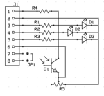
The schematic used is as follow:

Schematic.PNG

D1, D2 and D3 are RGB Led's and are in a Single Package.
R1, R2 and R3 are 220Ohm Resistor.
Jumper JP1 is used to short or by R4 (100 Ohm) Resistor.
R5 is 10K Pot, which is generally tuned to 10k value.
Q1 is photo-transistor L14G2, it has three pins photo-transistor and i didn't connected the base pin of this.

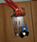
This circuit is assembled on a zero pcb as follow:

Circuit.jpg

And all this is circuit is placed inside a box, so that ambient light doesn't create any problem.

Inside Box.jpg

Photo-transistor is also surrounded by a Black tape so that the Led's light doesn't come directly to the photo-transistor.

I used Arduino to turn on the Red Led and Sense the Photo-Transistor output (Emitter-Ground Voltage), it is giving me 8 ADC counts and when i placed the Red Object inside that small box, the ADC counts goes to 14.
I did various other things like by passing the 100Ohm resistor, changing the value of pot and none of the things makes much difference.
I also tried the same test for Green and Blue lights with green and Blue Object, but the results are same as for Red object.

I am planning to replace the Photo-transistor with LDR and then will check the results.
Any suggestions, how can i improve this and why is my system is not giving me wider range.
 

II am planning to replace the Photo-transistor with LDR and then will check the results..

The detector should ideally have uniform sensitivity for the three radiations. Else you will be needing independent calibrations for the three light sources.

You will also need to calibrate with a white sheet: it should give the same reading for RGB sources.
 
I guess pin 2 is your ground connection?

I think you ought to play with resistor values going to the phototransistor, so that you get into a range where variations in light intensity cause electrical variations from the phototransistor.

A midway led intensity should cause a midway voltage from the phototransistor. R4 value is important in achieving this.

If R5 is too large then you lose sensitivity of response.

Also try taking output from its collector terminal, instead of its emitter.
 
The detector should ideally have uniform sensitivity for the three radiations. Else you will be needing independent calibrations for the three light sources.

You will also need to calibrate with a white sheet: it should give the same reading for RGB sources.

I got your point and will test with that.

- - - Updated - - -

I guess pin 2 is your ground connection?

I think you ought to play with resistor values going to the phototransistor, so that you get into a range where variations in light intensity cause electrical variations from the phototransistor.

A midway led intensity should cause a midway voltage from the phototransistor. R4 value is important in achieving this.

If R5 is too large then you lose sensitivity of response.

Also try taking output from its collector terminal, instead of its emitter.

Yes Pin 2 is ground connection.
And i will also try what you are suggesting and will report my observation back.
 

Status
Not open for further replies.

Part and Inventory Search

Welcome to EDABoard.com

Sponsor

Back
Top