Continue to Site

Welcome to EDAboard.com

Welcome to our site! EDAboard.com is an international Electronics Discussion Forum focused on EDA software, circuits, schematics, books, theory, papers, asic, pld, 8051, DSP, Network, RF, Analog Design, PCB, Service Manuals... and a whole lot more! To participate you need to register. Registration is free. Click here to register now.

[SOLVED] relationship between the complex input impedance of the antenna and S11?

Status
Not open for further replies.

B4M

Member level 2
Joined
Aug 3, 2016
Messages
47
Helped
1
Reputation
2
Reaction score
1
Trophy points
8
Activity points
318
Dear all,
I would like you to clarify a point that I don't understand very well.
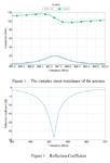
when an antenna resonate it means that the Imag part of the impedance is equal to zero, but while reading I found a paper with totally different results which I am attaching the confusing figures of the complex input impedance of the antenna and S11. Hope you could help me to understand or correct me if I have a wrong understanding of these things.
Thank you!
ImageNov.png
 

Zin seems to be 20+j*110 Ohm and S11 should be -1.16dB ???
 

yes,... but I still don't get it !:thinker:
 

You are apparently asking why the imaginary impedance part in resonance isn't zero for the specific antenna. Simple answer: we don't know but it's feasible. You can e.g. connect a reactance in series with a regular antenna. I presume you get the answer if you read the paper completely.

Additional point, you don't get matching without a respective conjugated reactant source impedance. The question is probably incomplete.
 

Thank you very much @FvM, yes this is my question..
I have read the paper seeking for an answer but the paper was not about giving explanations it is just showing simulation results with few comments, and I want to know what happens that allows us to get the resonance knowing that the imaginary part is not equal to zero?
Any ideas or references ?!
Many thanks!
 

Simply consider a definition of S11.
S11=(Zin-Z0)/(Zin+Z0), Z0=50ohm

(1) Zin=70ohm
|S11|=0.17

(2)Zin=50+j*10
|S11|=0.10

(3)Zin=200
|S11|=0.60

(4)Zin=35+j*10
|S11|=0.21

Or consider by Smith Chart.
 
Last edited:
  • Like
Reactions: B4M

    B4M

    Points: 2
    Helpful Answer Positive Rating
Hi,
All antenna are not a perfect resonnator ...
For example wire antenna impedance depend of its electrical lenght. At the frequency of use, the impedance could have a real part and an imaginary part.
For a rectangular patch, the cavity model or the line odel give us only a real part at the resonance frequeency.
Other antenna are not resonnator.
Bye
 
  • Like
Reactions: B4M

    B4M

    Points: 2
    Helpful Answer Positive Rating
probably you have good S11 because you have a normalizing impedance (see Z0 in pancho_hideboo answer) close to the antenna impedance.
 

Status
Not open for further replies.

Part and Inventory Search

Welcome to EDABoard.com

Sponsor

Back
Top