Continue to Site

Welcome to EDAboard.com

Welcome to our site! EDAboard.com is an international Electronics Discussion Forum focused on EDA software, circuits, schematics, books, theory, papers, asic, pld, 8051, DSP, Network, RF, Analog Design, PCB, Service Manuals... and a whole lot more! To participate you need to register. Registration is free. Click here to register now.

signal conditioning circuit Help

Status
Not open for further replies.

PRIYADHARSHINI PALANISAMY

Member level 2
Joined
Dec 23, 2013
Messages
52
Helped
2
Reputation
4
Reaction score
2
Trophy points
8
Activity points
371
Dear all ,


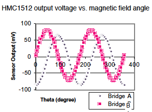
I want to produce 4-20mA current for magnetic rotation 90°,150°and 300°.I am using HMC1512 sensor to sense the angle.I have built the circuit for 90 degree rotation as per datasheet guidelines.I can get 1-3.7 volt for 0 to 90° rotation by using "bridge A" alone.Now i want to built the circuit for 150 degree and 300 degrees.How can i achieve this by using two bridges in HMC1512?

Thanks in Advance
 

It looks as though you wish to solve ambiguity? Looking at the diagram for one bridge, readings for 0 to 360 degrees occupy two sine cycles. So adding a second bridge produces unique combinations over the entire 0-360 degrees.

To do this using simple volt readings, find any way you can to make use of unique readings coming from either device. Example, minimum or maximum values, or zero crossings, etc.
Then position the devices so you get these unique readings at 90, 150, 300.

Consider having window comparators detect the positions you wish to mark. The 3914 IC makes a handy window comparator, although its resolution is coarse.
 
Thanks for your reply BradtheRad.Yes.I was confused.
Actually from 0 to 90 degree I get the values 1 to 3.7V.above 90 degree(90-180°) the readings decreasing from 3.7 to 1V.
If i feed this values to ADC how can i get the values for 150°?
For 90 degree it will get 3.7V as input..If it decrease again 3.7 to 1 V how the ADC will generate PWM for 150°?
Will it again assume as 90 deg to 0 degree?
 

The problem is to determine which of 4 quadrants you're in. I was ready to suggest that all you need to do is orient two bridges skew from one another. However as I think about it, you still get ambiguous readings, because the graph draws two sinewaves for every travel around the compass.

Copied from a pdf of the datasheet:

2439638700_1477294666.png


Therefore it may be necessary for you to look very hard for some variation in amplitude, or any irregularity, to allow you to resolve ambiguity. You might even need 3 bridges, although it certainly seems as though there should be a way to get by with 2.
 

Status
Not open for further replies.

Similar threads

Part and Inventory Search

Welcome to EDABoard.com

Sponsor

Back
Top