Continue to Site

Welcome to EDAboard.com

Welcome to our site! EDAboard.com is an international Electronics Discussion Forum focused on EDA software, circuits, schematics, books, theory, papers, asic, pld, 8051, DSP, Network, RF, Analog Design, PCB, Service Manuals... and a whole lot more! To participate you need to register. Registration is free. Click here to register now.

Amplifier Differential Input Question/Help

Status
Not open for further replies.

ljp2706

Advanced Member level 4
Joined
Mar 3, 2015
Messages
118
Helped
20
Reputation
40
Reaction score
20
Trophy points
1,298
Location
USA
Activity points
2,261
Hello,

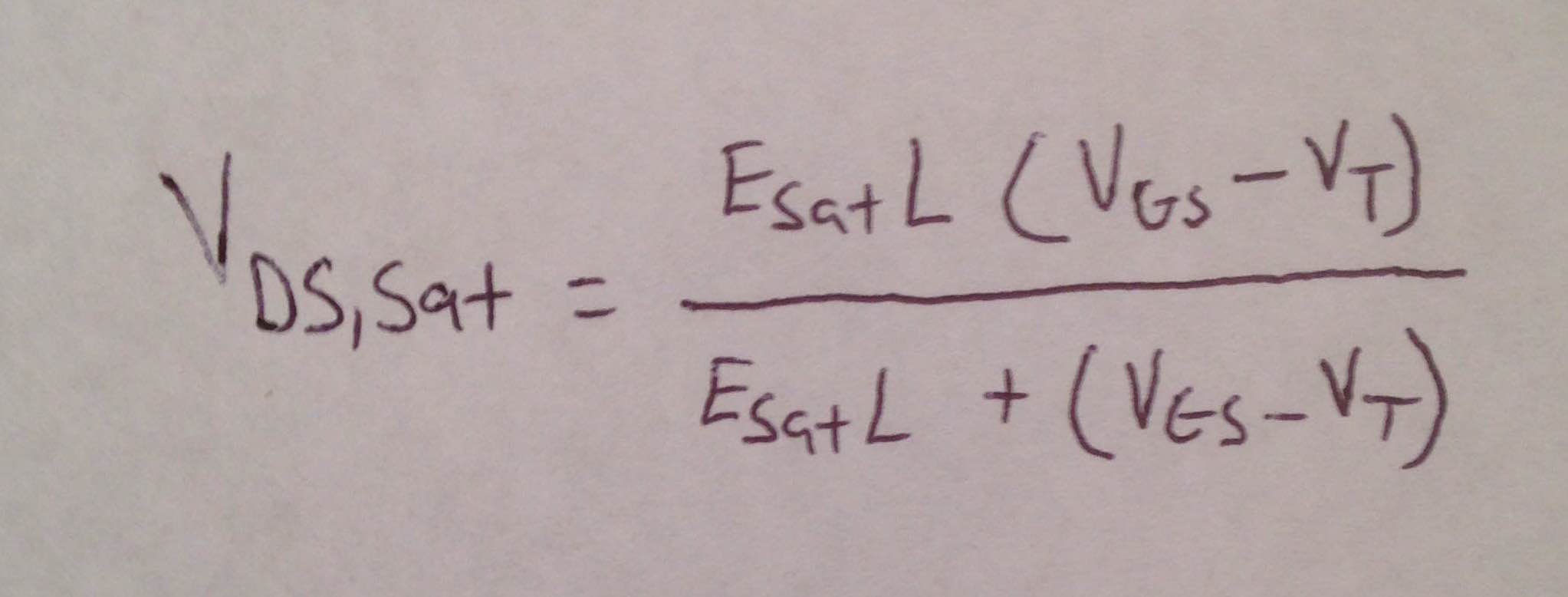
I am working in a sub 1 volt supply at the 14nm node. I have created an amplifier for a bandgap voltage reference. My issue that I was wondering if someone might be able to point me in the right direction lies with the differential input pair. When I run monte carlo, there are two points in which the VDS of the differential input falls below saturation for cold temperatures. I have tried to use helper transistors to keep the differential input in saturation, but it isn't working very well, are there any other methods I can attempt to implement to ensure the input remains saturated for all monte carlo points?

Thanks!
 

The first thing you can do is reducing vdssat, which would affect matching in a bad way. I don't know how things work at 14nm but in 28nm cascodes are hard to manage, so if you have cascodes you may want to look for alternatives.

If only 2 out of many monte carlo runs don't work, it's actually not a very big deal. Look at the distribution, the ones that don't work may be outliers and can never be fixed without drastic measures.
 

That is what I have done so far, I decreased VDSsat by making the input pair very wide. Cascodes do not work in this technology, there is not enough headroom for proper operation of the circuit I am working with.

And thanks for the information about monte carlo, I was always under the impression that they all need to pass.
 

Hi guys,

Allow me to ask you a question, since you are talking about Vdssat. In cadence, when you do annotate you get some of the mosfets parameters like vdsat, vds, vgs, vth, vbs, etc.

Now, when you are designing a circuit we know that, depending if you are designing for strong inversion, moderate inversion or weak inversion, how do you guys interpret the Vdsat, vds, vth, vds-vth?
 

Hi,

Many different pdks will actually allow you to display the vds,sat, which can be set to be shown in the DC OP points. vds-vth is wildly inaccurate in these technologies due to many effects, particularly velocity saturation. I'll provide a better explanation later on today once I have my notes in front of me.
 

Alright ljp. That's exactly what I think. So I was trying to get this kind of information, when it comes to design how we should interpret the information that cadence give us using the annotate dc bias points. Since the Vds-vth is no longer valid for sub-micron technologies, what's the best way to interpret the results. For examples, current mirror should be in strong inversion, so we need a large Vov, but we don't have Vov in that annotate function. SO how to know how deep in strong inversion is it, etc.

Regards.
 

In case you were unsure of how to set this vds,sat value I've included a couple images relating to it. Also, I have an image of the equation that I had mentioned for calculating vds,sat.

Just as a side note, accounting for velocity saturation, your vds,sat will actually be lower than it would be if you used vgs-vt so if your device is sized using the ideal square law model, then your device will still be in strong inversion.

Something that might be of interest to you would be inversion coefficient design, the gm/ID method. You could use this method to very easily size all your devices such that they are strong inversion. However strong inversion isn't usually used for most designs that I've seen in 14nm or 28nm, you can get better performance in moderate or weak inversion(if speed allows it). Of course it would depend on what you are designing/your purpose, as you said, it is best to design current mirrors in strong inversion for matching purposes.


That is what I have done so far, I decreased VDSsat by making the input pair very wide. Cascodes do not work in this technology, there is not enough headroom for proper operation of the circuit I am working with.

And thanks for the information about monte carlo, I was always under the impression that they all need to pass.

To be fair, most of the range occupied by the input pair is coming from their threshold voltage rather than their vdssat. It would still help, but you should also consider reducing vdssat for other current sources and adding a second input stage if you have to which would cover the range that it fails.

All the monte carlo points don't have to pass, but you should look at the distribution. For this purpose you can use gain at a certain input voltage range limitation for example (I don't know your project, so you need to decide on what to use, you may even look at waveforms but scalar is easier). If your specs are within 3 standard deviations about 99% of your devices will be within specs. If 2 standard deviations, 95, if 1, it would go down to 68%. People run monte carlo to find out these distributions, failure on an individual point is quite possible since there may be an outlier (although algorithms try to make it a meaningful distribution there's still randomness in it). The number of points that fail may even change with different runs if you're not using a monte carlo seed.
 

Status
Not open for further replies.

Part and Inventory Search

Welcome to EDABoard.com

Sponsor

Back
Top