Continue to Site

Welcome to EDAboard.com

Welcome to our site! EDAboard.com is an international Electronics Discussion Forum focused on EDA software, circuits, schematics, books, theory, papers, asic, pld, 8051, DSP, Network, RF, Analog Design, PCB, Service Manuals... and a whole lot more! To participate you need to register. Registration is free. Click here to register now.

Optocoupler circuit design

Status
Not open for further replies.

a.singh123

Newbie level 5
Joined
Sep 20, 2016
Messages
8
Helped
0
Reputation
0
Reaction score
0
Trophy points
1
Activity points
86
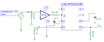
I need to design a optocoupler circuit as shown in the attached datasheet of IL300 optocoupler IC. I designed the circuit as shown in the first page of pdf. I used OPAMP OP-07. I did'nt used the output OPAMP in the circuit. I applied a sine wave of few hundred hertz at the input. It gets reflected at the output. Problem is that if I give sine wave at the input from 0V to 1V, the output gets clipped from negative side. If I give a DC shift of 0.3V, then output comes faithfully.
I want the output should follow input if input is from 0 to 1V. But output is getting clipped. please suggest me.

Abhishek
 

Attachments

  • IL300.pdf
    141.5 KB · Views: 108

The datasheet for the old OP-07 opamp shows that its output cannot go closer than about 2V from its negative supply that is ground in your circuit. The OP-07 needs to have an additional negative supply voltage, or use an opamp that has an output voltage that goes lower.
 
The datasheet for the old OP-07 opamp shows that its output cannot go closer than about 2V from its negative supply that is ground in your circuit. The OP-07 needs to have an additional negative supply voltage, or use an opamp that has an output voltage that goes lower.

I connected a negative bias at the -V pin of OPAMP instead of ground, and it is working perfectly. The circuit image is attached. For a input of 0 to 1V, it gives a output of 0 to 1V exactly. Thanks dear for your kind support. Thank you very much.
But one issue is that if I increase input above 1V, output gets clipped from above. I need input range from 0 to 2V. What should I do? I tried increasing power supply from 12v to 15v but it did'nt worked.

Regards,
Abhishek
 

Attachments

  • Optocoupler_finalckt.png
    Optocoupler_finalckt.png
    25.5 KB · Views: 156

Hi,

R1 and R4 should have the same value to get best performance.

If you need higher input voltage range, then add a resistor between VG1 and R3, so it forms a voltage divider with R3.

Klaus
 

Easy to see that output photodiode saturates with 2V input due to large R4 value. Won't happen with R4=10k.
 

Status
Not open for further replies.

Part and Inventory Search

Welcome to EDABoard.com

Sponsor

Back
Top