Continue to Site

Welcome to EDAboard.com

Welcome to our site! EDAboard.com is an international Electronics Discussion Forum focused on EDA software, circuits, schematics, books, theory, papers, asic, pld, 8051, DSP, Network, RF, Analog Design, PCB, Service Manuals... and a whole lot more! To participate you need to register. Registration is free. Click here to register now.

Isolated DC/DC, Input 9V to 36V, output 18V4A

Status
Not open for further replies.

max.wangxin.sh

Junior Member level 3
Joined
Sep 9, 2016
Messages
25
Helped
2
Reputation
4
Reaction score
2
Trophy points
3
Location
Shanghai, China
Activity points
170
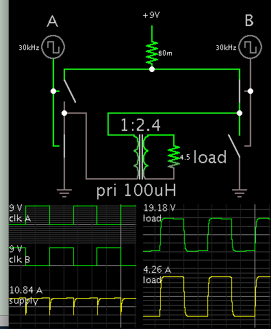
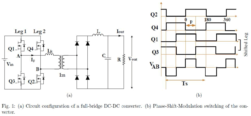
I was asked to design the converter for auto application. It still has rough requirements on the whole size and EMC performance. Anyway it seems hard to decide the main topology at first. Its input range is wide and output power is not low. I do not know for sure the flyback is the best. would you please share any guidance?
 

To step up 9V requires that you draw 8A average from the supply. Call it 10A with losses. It must be condensed into waveforms occupying one half of the cycle (call it 60%). This translates into waveforms approaching 30A peak. To achieve this there can only be bare minimum parasitic resistance.

A full H-bridge might be a suitable option. Then the waveforms have lower current peaks.

The flyback also has cousins such as the SEPIC and Ćuk (or boost-buck).
 

I think I would take two bites at this particular problem.

First I would build a non isolated boost converter to convert the incoming 9v to 36v up to something just slightly above 36v.

Then I would build a full bridge that always runs at full maximum duty cycle through a transformer to generate the isolated 18 volts. As the primary voltage will always be up around 36v, the primary current will be acceptably low, and huge mosfets and heat sinks should not be required, efficiency of the second stage should be pretty good.

All the regulating would be done by the boost converter on the input side which will need to be built to handle high current, maybe 10 to 12 amps, but its only one mosfet.
Boost converters have a fairly constant input current, so should be the easiest topology to get through conducted emissions.

The four mosfets in the bridge can have their gates driven by a single transformer with four secondaries, because the duty cycle will always be a non varying 50% (less dead time).
The gate drive transformer could be driven by a flip flop such that the bridge runs at half the frequency of the boost stage and operates in phase.
The boost stage is pretty simple and can run just about any suitable PWM controller.

At least that is how I would probably do it...
 
Last edited:
72W, 1:4 input voltage range sounds like being basically suited for a flyback converter.
 

Flyback is probably the way to go, assuming OP doesn't need very high efficiency (>80%) and can obtain a suitable transformer. Second choice would be forward converter, or maybe push pull.
 

BradtheRad, many thanks for your kind reminding. I agreed with your analysis. but the full H-bridge seems more complicated. can you recommend any IC to make it? I want to evaluate its complexity from the typical schematic.
 

Warpspeed, I appreciated your comprehensive sharing greatly. Your idea is amazing but the cost would be much higher. and the size would be another problem. It is hard to MP. another two question, 1) why does it require four isolated gate drivers? 2) how about the load regulation for the open-loop full bridge?

FvM, thanks a lot for your answer. Frankly i think it hard for the flyback. 72W means CCM. 1:4 means high duty cycle range. can you share one examples for this basically situation.?

mtwieg, thanks a lot for your suggestion. It is hard to make it with flyback because of its 72W and 1:4 input voltage. do you think it is easier than forward and push pull?
 

i woudl just do coupled SEPIC, as unlike the flyback, it wont need the primary clamp....this actually often makes the sepic slightly better than flyback in effciency.

you wouldnt need to sandwich wind with a sepic....a bit of leakage will be ok with sepic.
as you say you dont need isoaltion.

- - - Updated - - -

or you could just throw an LT8705 based buck or boost at it.
 

Warpspeed, I appreciated your comprehensive sharing greatly. Your idea is amazing but the cost would be much higher. and the size would be another problem. It is hard to MP. another two question, 1) why does it require four isolated gate drivers? 2) how about the load regulation for the open-loop full bridge?
If the second stage uses the forward converter bridge topology, it will require four mosfets, and the gates of the upper two will need isolated gate drive. The simplest solution to that is a pulse transformer, which can also drive the lower mosfet pair.
Fewest components and less that can go wrong.

The full bridge just works flat out all the time making it both simple and efficient.
The 18 volt dc output is sensed and fed back to the boost converter to provide overall output voltage regulation. That will take care of not only input variations, but also compensate for the regulation of the bridge converter/transformer/rectifier.

Flyback is definitely the simplest, but the problem will be dc input current will be about ten amps at 9v input. Peak current in the primary will have to be at least 40 amps at maximum duty cycle.

That poses two problems, conduction losses at 40 amps in both mosfet and transformer primary are going to be relatively high.
Those 40 amp pulses will need to be filtered out with a very large input electrolytic and associated input filter to achieve a smooth 10 amp dc input current.

Dc input current will need to be very smooth to pass conducted EMC levels.
This is going to be a very major problem for you.

A boost converter needs an input inductor, but the cost and size of that may be less than the required input filter for a flyback.

Try a flyback first, but the extremely high pulsing input and output current could be an insurmountable obstacle to producing a cost effective and small electrically quiet power supply.
 

Trees, thanks a lot for your answer. I know LT8705 and It is popular for non-isolated converter with wide input voltage range. Anyway the customer requires isolation converter.
 

mtwieg, thanks a lot for your suggestion. It is hard to make it with flyback because of its 72W and 1:4 input voltage. do you think it is easier than forward and push pull?
Flyback is uniquely suited to large ranges of Vin/Vout, and other topologies will require a larger duty cycle variation to cover the same range. This is one of the reasons it's used for universal AC-DC converters and benchtop supplies.
 

This is one of the reasons it's used for universal AC-DC converters and benchtop supplies.
Yes its a very practical and popular topology for low and medium power direct off line power supplies.

But consider the input voltage range might be something like 90v to 360v dc.
At the power level we are discussing here, there might be one amp dc input at 90v, and four amps at the peak of the primary current ramp. Not too difficult.

Here we have 9v to 36v input dc. Ten amps input, with 40 amps at the peak of the primary. Conduction loss is I squared R so its not ten times but 100 times as difficult to deal with.
And remember we are talking about the exact same power level.

Things are very different when selecting the most suitable topology for either high or low voltages.
 

BradtheRad, many thanks for your kind reminding. I agreed with your analysis. but the full H-bridge seems more complicated. can you recommend any IC to make it? I want to evaluate its complexity from the typical schematic.

There are IC's for driving motors which contain an H-bridge. (I have not worked with such IC's.)

For comparison here is a simple H-bridge which steps up 9V to 19V 4A. The supply provides a smooth (more or less) current waveform.

1473750900_1473559141.png


The switches turn on and off (like an array of N & P devices).

Parasitic resistance is 1/10 ohm total (each switch set to .01 ohm). You lose a volt, or 10W.

If parasitic R is 2/10 ohm then you must increase current draw to 13A. You must increase step-up ratio needs to be 3x (to compensate for 2.2V drop). Power loss approaches 30W.
 

Here we have 9v to 36v input dc. Ten amps input, with 40 amps at the peak of the primary. Conduction loss is I squared R so its not ten times but 100 times as difficult to deal with.
And remember we are talking about the exact same power level.

Things are very different when selecting the most suitable topology for either high or low voltages.
Things are not completely different.

First point to consider is that any variable voltage ratio converter topology will somehow suffer from the 1:4 duty cycle variation, as long as it doesn't implement switched transformer taps or similar structure switching. I agree with treez that the weakest point of the simple flyback topology is probably the need for a primary voltage clamp. But in this regard, there isn't much difference to a wide range off-mains switcher with typically >1:3 voltage variation.

If you are afraid of the flyback transformer design problems, a PSB with secondary storage inductor can be a more relaxed approach.

I admit that your suggested boost topology has some advantages, particularly continuous input current. It can be easily extended to multi phase for higher currents.
 

Warpspeed, generally I used self bias circuit for the top mosfet driver. and the whole loop control from Fb voltage of the full bridge to the boost converter would be too complicated to compensate. flyback or one stage full bridge seems acceptable. again thanks a lot for your professional analysis and sharing.
 

FvM, most small output power flyback is convenient for wide input voltage because of its DCM or varied frequency. anyway I have to make the flyback in CCM for its 72W for less current stress. and then the duty cycle variation would be problem if the switching frequency is constant. btw, i do not understand a PSB with secondary storage inductor. can you provide more explanation?
 

and then the duty cycle variation would be problem if the switching frequency is constant
The only problem with keeping CCM is to design sufficient flyback transformer inductivity. Any other topology e.g. boost converter will face the same problem in some way.

i do not understand a PSB with secondary storage inductor
I'm referring to well-known standard topology

IJAREEIE-1984-g001.gif
 

Things are not completely different.

First point to consider is that any variable voltage ratio converter topology will somehow suffer from the 1:4 duty cycle variation, as long as it doesn't implement switched transformer taps or similar structure switching.
Only for buck-derived converters. For a buckboost derived converter, like the flyback, the duty cycle variation is less (assuming CCM). For example, a buck derived converter with duty cycle range 0.2-0.8 gives gain range between 0.2-0.8 gain range, while a flyback will give a range of 0.25-4, a factor four improvement in the ratio.
 

maybe think about active clamp forward topology. i calculated with power stage designer from TI for your specs and get adequate parameters (i set 62% max duty cycle). 10.7A RMS current (9Vin) in power mosfet, picking 10mOhm mosfet you get 2.2W static looses. +2W switching looses. its ok for TO220 with heatsink.
i have designed 100W dc/dc 20V-36V/24V isolated active clamp forward converter with efficiency 90%. transformer on ETD29.
 

This sure sounds to me what the push pull was designed for. Single switch voltage drop and with alternate switching a fairly constant current flow, so less EMI problem and much smaller input capacitor than a flyback.
 

Status
Not open for further replies.

Similar threads

Part and Inventory Search

Welcome to EDABoard.com

Sponsor

Back
Top