Continue to Site

Welcome to EDAboard.com

Welcome to our site! EDAboard.com is an international Electronics Discussion Forum focused on EDA software, circuits, schematics, books, theory, papers, asic, pld, 8051, DSP, Network, RF, Analog Design, PCB, Service Manuals... and a whole lot more! To participate you need to register. Registration is free. Click here to register now.

measuring battery temperature

Status
Not open for further replies.

Derun93

Member level 3
Joined
Nov 9, 2015
Messages
60
Helped
0
Reputation
0
Reaction score
0
Trophy points
6
Activity points
532
Hi, I need temperature sensors to measure battery cells' temperature by one by. The cell are connected in series so I could not find a temperature sensors which resists at 17V or more. I looked at LM35 but I could not figure out how to I connect it to battery cells.
Thank you
 

The temperature sensor does not need to be electrically connected to the device which it monitors. It can draw power from a different source. Most likely you'll put the LM34/35 in a resistor network, which creates a voltage which you feed to an op amp (or instrument).
 

Hi,

Maybe this circuit is similar to your needs:

"FIGURE 3. ∆T DETECTOR CIRCUIT"

It's on page 7 of the pdf ("Battery Charging"), it requires 2 LM35s per battery, presumably if you use several the circuit would only need one to measure ambient temp; LM35 is okay to 30V.
 

Attachments

  • snva557.pdf
    146.6 KB · Views: 235

LM35 is an excellent choice of sensor.
Epoxied onto a rectangle of aluminium or stainless steel, each metal sheet can then be placed under each individual cell. It may possibly need some thermal insulation under the metal sheet which could be either wood or rubber.

Cells change in temperature very slowly, and the above method has been proven to work quite well.

A simple way to build a digital temperature readout for an LM35 is to use a low cost digital amp meter. If you can find one that reads up to 50.0 Amps at 75mV, all you then need will be two resistors, 6K8 and 1K2 to drop the 500mV from the LM35 down to 75mV.

You then have a very nice low cost 0 to 50.0C digital thermometer with a very convenient 0 to 500mV output.
 
Last edited:

If you can find one that reads up to 50.0 Amps at 75mV, all you then need will be two resistors, 6K8 and 1K2 to drop the 500mV from the LM35 down to 75mV..

Why so high current is involved? It is basically a voltage device depending on the effect of absolute temp on the change in the band gap edge...
 

Why so high current is involved? It is basically a voltage device depending on the effect of absolute temp on the change in the band gap edge...
You have missed the point.
A digital dc amp meter requires an input of 75mV dc not fifty amps.
With an amp meter with 50mV input, its more difficult to arrange an exact 9:1 resistor ratio for the required voltage divider.

We need a suitable temperature scale, and 0 to 50.0 reading is probably the most useful temperature scale to have for many applications.

A 5 Amp, or a 500 Amp, or 500mV scale puts the decimal point in the wrong place. Most of these panel meters have a multiplexed display, and its not really possible to move the decimal point away from the original position.

If you use an LM35, and two 1% resistors of 6K8 and 1K2 it will in practice usually read within one degree without even having to tweak the pot on the panel meter.
 

can you share your battery's connection? you can use NTC with resistor divider if the voltage of the battery pack is proper.
 

I can not understand exactly what you are saying , Mr.Warpspeed. If you share your connectıons, it will be more clear.
Thank you.
 

I am sorry but I still could not figure out how I connect LM35 to a single battery cell.
 

Hi,
Does your planned circuit have it's own power supply? I'm not quite sure what you mean in the last post about connecting the LM35 to a single battery cell, sorry, hope this helps.

Glossing over the layout guidelines, for example section 10 in the TI datasheet (this is the version I have: SNIS159E –AUGUST 1999–REVISED JANUARY 2015) the LM35 plastic body measures the temperature, so you stick/glue/affix that to the battery body (or whatever you are measuring), and pins Vs and GND are connected to the separate power supply used to power the control circuitry.

I do not know if you can power the LM35 from the battery being measured directly, as a) the LM35 leads also influence temperature reading, and b) not something I've thought about before, I thought you had one power supply/battery for the measurement circuit, and the measured batteries were being measured by surface temp of each cell.

However, reviewing the "Battery Charging" app note from yesterday, page 7 schematic, it seems to explicitly show the LM35 powered by the battery being measured, and the rest of the control/measurement circuitry powered by an external power source of 8 - 30V, with both grounds/0Vs connected, so presumably you just need to connect the LM35 pins Vs and GND to the battery + and - respectively, and "Out" goes to whatever device you are using to process the LM35 output voltage. I assume you still need the IC silicon/plastic body stuck to the thing having its temperature measured.
 

Hi,

Derun93:
It seems you have an idea, maybe sone picture in your mind, or maybe some restrictions....we need to know.

Please give a more detailed description what you want to do. And why. A picture could be helpful, too.

Klaus
 
eBay has 75mV 50A analog and digital panel meters.

Instrument 85C17 DC 0-50A AMP Analog Panel Meter Ammeter S*

DC 50A Digital Ammeter Amp Current Gauge Meter Blue LED 50A/75mV Shunt Resistor
 

eBay has 75mV 50A analog and digital panel meters.
Yup.
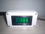
Here is My room thermometer.
Its not a great picture the flash has washed it out, it looks a lot better than the photograph.
The black dot on top of the plastic box is the LM35.
Thermometer.jpg
 

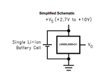
I am gonna measure temperature of each lithium-ion cells and I have 4 cells connected in series. So, when the cells are fully charged, the total voltage will be 4.2*4=16.8. In the picture, LM60 are connected to a cell in parallel but lm60 works at max10V. I am wondering that could I do same connections with LM35 Or other temperature sensors.
Thank you.
lm60.png
 

Hi,

could you please try to give all informations at once. Still a lot unclear.

* are the cells all fixed connected together or can you disconnect them so they are individual?
* as suggested before: can´t you supply all sensors from one cell, but put the sensor mechanically to the cell(s) you want to measure?
* do you have access to all 5 nodes when you connect the cells in series?
* can´t you use sensors with SPI so you can connect the datalines with optocouplers?
* how often do you want to measure --> datarate?
* what temperature resolution and accuracy do you want?
* How big is one cell? (mechanical dimensions)
* What do you want to to with the temperature information? Isn´t a binary signal "overtemperature" per cell sufficient?
* is it possible to use an external power supply instead of cell voltage (like uController supply, all four sensors connected to to a I2C bus. Power and data)

Klaus
 

Hi,

They seem to have the same pinout, but if as you say they are connected in series, no idea of where you connect intermediate LM35s or LM60s to their respective grounds, ...but really, perhaps instead of just asking "Can I use an LM35?" every two posts I honestly and respectfully think you should post a schematic of what you want to do as the snapshot of the LM60 datasheet doesn't have much in relation to what your last post says.
 

Mr.Klaus, with all my respect, I am newbie at electronic and trying to learn information about electronics so please ignore my mistakes, I am trying do my best. I would want to give all information at once but I could not realize whether this given information is enough or not.
The cells are individual and I am connected in series manually.
I want to measure each cell and each temperature sensor is supplied by its cells.
I have access all nodes.
I want to measure them each 10 seconds.
Accuracy +-5C is proper and resolution is not my priority.
Cell Weight: 7.6 grams (0.3 oz.)
Cell Volume: 3.8 cubic centimeters (0.2 cubic inch)
Detecting Over temperature per cell is sufficient.
It is possible to use external power source but I do not prefer to use.
can´t you use sensors with SPI so you can connect the datalines with optocouplers? for this question, I do not have enough information but I will search for it.
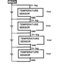
In the picture Mr.d123, I want to connect temperature sensor like that. Lots of temperature sensors has 3 leg and one of the V+, one of them gnd and Vout. I am wondering that instead of connecting ground leg to the negative leg of the cells, does it work? or if I just connect ground leg to the ground, what temperature sensors measure?
Thank you.
(sorry for the picture, I made it in the phone.)
temp.png
 

Hi Derun93,

I personally think that wouldn't work, I'm afraid, but there's nothing to stop you simulating it in a free program like LTSpice to see what happens, and there are many other free simulation programs, if you're interested the forum section called "Software problems, hints and reviews"
https://www.edaboard.com/forums/14/

or possibly also in PCB Routing Schematic Layout software and Simulation
https://www.edaboard.com/forums/15/

I don't remember exactly which/who, but there are at least a couple of threads regarding simulating the LM35, and/or finding a model for a simulator which could help.

"or if I just connect ground leg to the ground, what temperature sensors measure?" I think it has already been mentioned in this thread: the LM35 plastic/silicon body is the temperature sensor, not the +V and -V pins, the +V and -V pins just power the integrated circuit so it can output the 10mV per degree Centigrade through the Out pin.

Unless some-one offers a better suggestion, I'd just connect the +V of each of the 4 LM35s to the top of the first battery, and the -V/GND pins of the LM35s to the -V of the bottom battery, that's what I'd recommend. ...I say so because you said you don't want to use an external power supply.

Because I've never used the LM35 powered by more than 5V, even if it can be powered up to 30V according to the datasheet (it says 4 to 30V), I'd also pay attention as to whether ~18V makes it a little hot, and a dropping resistor or some 5.1V Zener diodes would be helpful.

Datasheets are a PITA for newbies like you and I, you have to decipher them by re-reading them until the graphs and descriptions, and obscure clues you glean from application hints or the "electrical characteristics" sections make the device you are using comprehensible.

Good luck!
 
It has been previously suggested to isolate temperature sensors from battery cell terminals. For some reason you rely on referencing each battery sensor to cell minus terminal. This can make sense if the temperature sensor is part of a battery management system including cell voltage monitoring and possibly a charge balancing circuit and separate controllers for each cell. Obviously there must be an isolated data link between the controllers and a host system.

But you didn't address overall system design in this thread. In so far it's still unclear why you prefer non-isolated temperature sensors.
 
Derun93, why not power these temperature sensors from the + terminal of the top cell and - thermal of the bottom cell? and the output voltage of these temperature sensors would have the identical GND and can read by ADC easily.
 

Status
Not open for further replies.

Part and Inventory Search

Welcome to EDABoard.com

Sponsor

Back
Top