hooksolutions
Newbie level 3
I have a machine that has a DC motor.
It has a brake using a SSR.
I bought this machine new 15 years ago and have used it every day since.:grin:
now when I try to run the machine, it throws the AC 8 amp breaker. It pulls up to 20 amp before throwing the AC breaker.:-(
If I unhook the SSR, the machine runs fine except when it shut off it keeps spinning, no brake.
I am trying to check the SSR.
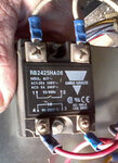
if I hook up #3 and #4 and turn on the machine I have 110V at #3.
It looks to me like #1 and #2 should be open at some point. what opens and shuts #1 and 2?
When I push the start button, the DC motor spins and then when the timer shuts off the motor I would assume this would close #1 and #2 to short out the DC motor to work as a brake, but that is what has quit.
I bought a new relay and it didn't help. I think the SSR is good but don't know what should happen. when I turn the power off on the relay nothing changes at #1 and #2.
what am I doing wrong when checking the SSR?
It has a brake using a SSR.
I bought this machine new 15 years ago and have used it every day since.:grin:
now when I try to run the machine, it throws the AC 8 amp breaker. It pulls up to 20 amp before throwing the AC breaker.:-(
If I unhook the SSR, the machine runs fine except when it shut off it keeps spinning, no brake.
I am trying to check the SSR.
if I hook up #3 and #4 and turn on the machine I have 110V at #3.
It looks to me like #1 and #2 should be open at some point. what opens and shuts #1 and 2?
When I push the start button, the DC motor spins and then when the timer shuts off the motor I would assume this would close #1 and #2 to short out the DC motor to work as a brake, but that is what has quit.
I bought a new relay and it didn't help. I think the SSR is good but don't know what should happen. when I turn the power off on the relay nothing changes at #1 and #2.
what am I doing wrong when checking the SSR?