Continue to Site

Welcome to EDAboard.com

Welcome to our site! EDAboard.com is an international Electronics Discussion Forum focused on EDA software, circuits, schematics, books, theory, papers, asic, pld, 8051, DSP, Network, RF, Analog Design, PCB, Service Manuals... and a whole lot more! To participate you need to register. Registration is free. Click here to register now.

discontinuous flyback transformer switching,100Khz , 8A

Status
Not open for further replies.

raja_rajan

Newbie level 6
Joined
Jul 25, 2016
Messages
12
Helped
1
Reputation
2
Reaction score
1
Trophy points
3
Activity points
129
hi,
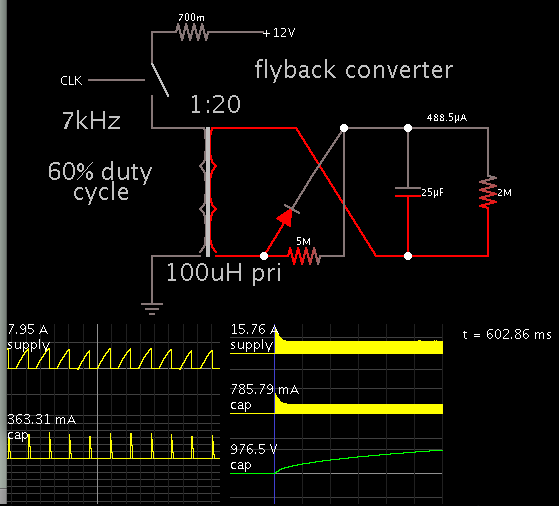
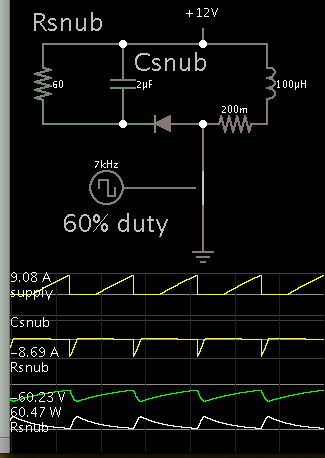
I am using discontinuous flyback transformer of current rating of 8A and frequency is 100khz with 60% on and 40% duty cycle. I am using fod3184 optoisolator to drive the igbt which supports upto 150khz. using this transformer, i have to charge 25uf/1100v capacitor upto 950v. while connecting the capacitor it will charge upto 100v and didnt charge after that. while checking with scope i got pwm fod3184 without connecting capacitor, but connecting capacitor i got pwm charging upto 100v and fod3184 stops pwm after that because of loading.

100khz pwm is generated from lpc2148 and given to fod3184. It supports upto 250Khz, 3A.

Tansformer Spec are:

Turn ratio: 1:40.
input-12v dc;
output-2500v. while putting two high speed diodes uf5408, i am getting 1400v dc

Application:

I want charge the capacitor every 1 Sec upto 950. (Medical laser)

can anyone please give solution for the problem?.
 

Your post is missing significant observations respectively measurements. Tripping FOD3184 UVLO would be my first guess. Or there are other control mechanisms not mentioned at all like transistor peak current detection.

Please post full schematic and meaningful measurements.
 

Hi FvM,
I had attached schematic. Please see the file and tell me if any thing is wrong in the schematic.

Thank you for your response.
 

Attachments

  • schm1.pdf
    14.2 KB · Views: 133

There's nothing wrong with the schematic as such, it might miss primary snubber or voltage clamp, depending on the transformer properties.

But it's impossible to determine the problem cause without seeing actual waveforms.
 

you need 2500V an put output cap 1100V rated?
two 1000V diods connected in series to increase reverse voltage?
 

Wow, that is an 80:1 voltage step up ratio (12v to 950v).

The problem with that will be the 40:1 turns ratio, and the inductance and stray capacitance of the secondary will end up being uncomfortably high.
That usually results in a relatively low self resonant frequency of the secondary.

While running low voltage flybacks at 100 Khz and beyond, is done all the time, it all becomes much more difficult and much less efficient to run high voltage at such a high repetition frequency.

I just cannot imagine a 40 turn secondary having a low enough self resonant frequency.

You may need to get a more meaty core and lower the frequency considerably.
 

No, according to manufacture details. The transformer will give 2200v for 12v input.but i am getting close to 3000v ac,now i use three diodes to increase reverse voltage protection and getting 1400v across diode. the transformer is designed to charge a 25uf/1100v capacitor upto 1100v in 0.8 secs. Its turn ratio is 8:320.
 

The output charges a capacitor. It causes different behavior than with a resistive load.

Here is a simulation.
The transformer primary gets 8A.
12V is stepped up 20x.
It charges the capacitor to 976V in 6/10 second.


Each charging pulse is 3/4 A. This may be severe for the capacitor to withstand.
However the OP specifies a step-up ratio of 40x, creating charge pulses at a lower Amperage.

At startup the output Ampere level is unrealistic. Yet it may indicate the operating frequency should be faster at startup, then slow down as the capacitor reaches 200V or so.
 
Check your power source, it may be dipping (volts going low) during the charging process, - due to your simple control saturating the transformer...
 
Hi,
how to calculate rcd snubber for the circuit.
 

how to calculate rcd snubber for the circuit.

The capacitor quickly absorbs the spike produced across the primary. During the remainder of the cycle, the capacitor discharges through the resistor.

Capacitor voltage soars if C value is too small, or R value is too high.

R dissipates power therefore it needs sufficient watt rating.

If R value is too low, then it creates a circulating loop through the primary winding. Current travels around this loop during the last half of the cycle, when it should not. It wastes power.
 

Hi,
For snubber circuit, any specific value for capacitor. can i use ordinary diode like 1N4007 ?.

I am using 600v,(55A @25c,27A @100C) igbt for 8A flyback transformer. but primary volt is 12, secondary volt is too high upto 3kv. Is it necessary to put a snubber circuit?.
 

I am using 600v,(55A @25c,27A @100C) igbt for 8A flyback transformer.
Pretty optimistic using an IGBT at low voltage, and at 100 Khz for flyback switching.
Why not a mosfet ?

This is all so very wrong, the choice of components and switching frequency is just a horrible combination.

And no, a dead slow 1N4007 power diode is not going to work either at 100 Khz.
An ultra fast diode, maybe a UF4007 might stand a fighting chance.
 

how to calculate rcd snubber for the circuit.

The RCD type appears to be used frequently so it must be effective. It needs to absorb spikes of 8A, if that is going through your primary at shut-off.

Simplified simulation gives the general idea.

5891064100_1470087140.png


Based on your operating frequency, etc., you'll need different values.
 

Hi,
Do you suggest us a mosfet, which supports 100Khz, 200v and >20A?.

Regards,
rajarajan
 

Your original post suggested this inverter was powered from 12v dc ?

Tansformer Spec are:

Turn ratio: 1:40.
input-12v dc;
output-2500v. while putting two high speed diodes

I suggest you check the saturation voltage of your IGBT and realise you are going to lose at least 10% of that incoming 12v in conduction loss.
Also check the IGBT turn off time, and see how that compares to a 5uS half switching cycle and work out how much power is going to be lost in turn off switching loss compared to how much power actually makes it into the secondary.

A mosfet will be vastly superior on both counts.
 

I believe your question is still why the capacitor charging stops at 100 V. Although I agree that an IGBT isn't first choice for the primary switch, it can work.

Unfortunately we can only guess about the problem without meaningful measurements, e.g. IGBT gate and collector waveforms.
 

Hi,
I am using a feedback resistor divider network to cutoff the charging capacitor to particular volt.

If the capacitor has 750 volt through the feedback resistor, I will get 2 to 3v which is given to adc and when the reference value is matched the pwm is off, capacitor stops charging.

how to isolate the micro controller (low side) and high side ground or how read the adc from high side?.
 

Attachments

  • div.pdf
    5.2 KB · Views: 99

Status
Not open for further replies.

Part and Inventory Search

Welcome to EDABoard.com

Sponsor

Back
Top