Lorenz.zulu
Newbie level 3
Hi everybody,
I'm looking for a solution for my controller which has its central unit and/or displays out of work.
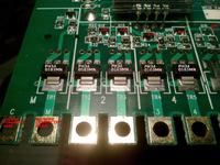
I'm going to upload a photo of this controller where you can see the "operational area" (at the end of which various wires must be connected). There, nearly 13V arrive (in a track where I drew a left pointing arrow in red), crossing the 4 transistors (Q15, Q14, Q13, Q12 plus Q11 which is of no interest since no wire has never been connected to "M" terminal) that release current (when required) letting it flow until the 4 terminals in order to activate the sprinklers' stations.
As you can imagine, these 4 transistors normally get the signal arriving from the central chip but this is not possible now due to the COB malfunctioning.
What I need to know is whether it is possible to add a timer switcher component able to manage the current flow for 2 different lines (I could reduce the sprinklers' lines from the current 4 to 2 by connecting the relative wires in couple to 2 of the 4 terminals). Those 13V must flow towards 1 transistor for 1 hour, then flow to another transistor for another hour. That's all.
So I could connect, for example, 2 wires on terminal n.1 and the other 2 on terminal n. 4. I could then bridge base and collector (via a resistor) of the 2 transistors commanding those 2 lines (Q12 and Q15 in our example). For the first hour of power on, I could connect the first 2 wires to the terminal n.1.
Then I could get back to the controller, turn it off, disconnect the first 2 wires, connect the other 2 to the terminal n.4 and finally plug in the transformer again. I think this procedure would take less than a minute but it would be effective.
The ideal would then be to find a way to avoid the manual switch between the 2 lines, as I said before. But how?
As the 4 transistors are in series, I could break the track to separate them but I need something earlier able to switch between lines and manage timing.
All tasks done only by a chip? Are there other solutions (even connecting an external device, since I don't have space problems)?
Here are the electrical specifications regarding the station output power:
- 24 VAC (the "C" common terminal)
- 6 VA (0.25 amps) per station maximum
- 6 VA (0.25 amps) pump start/master valve
- 12 VA (0.50 amps) total load
I'm looking for a solution for my controller which has its central unit and/or displays out of work.
I'm going to upload a photo of this controller where you can see the "operational area" (at the end of which various wires must be connected). There, nearly 13V arrive (in a track where I drew a left pointing arrow in red), crossing the 4 transistors (Q15, Q14, Q13, Q12 plus Q11 which is of no interest since no wire has never been connected to "M" terminal) that release current (when required) letting it flow until the 4 terminals in order to activate the sprinklers' stations.
As you can imagine, these 4 transistors normally get the signal arriving from the central chip but this is not possible now due to the COB malfunctioning.
What I need to know is whether it is possible to add a timer switcher component able to manage the current flow for 2 different lines (I could reduce the sprinklers' lines from the current 4 to 2 by connecting the relative wires in couple to 2 of the 4 terminals). Those 13V must flow towards 1 transistor for 1 hour, then flow to another transistor for another hour. That's all.
So I could connect, for example, 2 wires on terminal n.1 and the other 2 on terminal n. 4. I could then bridge base and collector (via a resistor) of the 2 transistors commanding those 2 lines (Q12 and Q15 in our example). For the first hour of power on, I could connect the first 2 wires to the terminal n.1.
Then I could get back to the controller, turn it off, disconnect the first 2 wires, connect the other 2 to the terminal n.4 and finally plug in the transformer again. I think this procedure would take less than a minute but it would be effective.
The ideal would then be to find a way to avoid the manual switch between the 2 lines, as I said before. But how?
As the 4 transistors are in series, I could break the track to separate them but I need something earlier able to switch between lines and manage timing.
All tasks done only by a chip? Are there other solutions (even connecting an external device, since I don't have space problems)?
Here are the electrical specifications regarding the station output power:
- 24 VAC (the "C" common terminal)
- 6 VA (0.25 amps) per station maximum
- 6 VA (0.25 amps) pump start/master valve
- 12 VA (0.50 amps) total load

Last edited by a moderator: