Continue to Site
Follow along with the video below to see how to install our site as a web app on your home screen.
Note: This feature may not be available in some browsers.

I have built this noise source and tried different zeners. I have used 8.2V battery.
I cannot notice any noise in the scope. Why it does not work?
What kind of noise power should I expect?
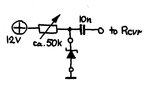
Try this circuit, it will produce several volts of peak to peak wide band noise output.
Any available small NPN transistors should work quite well.
Its the reverse base emitter junction of the first transistor that creates all the noise, the collector is left unconnected.
This will light up your whole oscilloscope screen a nice even green glow at any reasonably fast sweep speed, it amazing.
View attachment 130799
Hardly 30 MHz with the given circuit dimensioning. Presume you know a little bit about RF amplifiers and see why the bandwidth is limited.Will the useable noise cover 1-30MHz?
Small signal BJT BE breakdown voltage can be expected around 7 V, means the circuit needs 9 - 10V supply voltage.Will it operate ok at 9V or 8.2V as it is, or do I need to make any changes to the circuit?
It impressed me greatly at the time for such a simple circuit which is why I kept it for future reference.
Just had a look through my stock of transistors here, trying to solve the mystery.Hey the 2n2904 are PNP transistors, not NPN as shown in the schematic?