et413
Newbie level 2
I have a remote solar installation with six lights that I currently monitor with a GSM voltage monitor. Because of its location, it is subject to the occasional vandalism by bored locals. Specifically, they love to shoot out the lights.
I purchased and installed six DC current sensors and controlled each with one light. The sensors have a relay with a common, normally open contact and a normally closed contact. When current begins flowing (the lights are now burning) the relay changes states.
So I ran the battery feed to the GSM monitor through all the relays in a series circuit. So now if all lights are burning, I properly receive the voltage reading from the battery bank. But when a light is out (any light), the series circuit is broken and I get an alarm because of low voltage.
This is a big improvement. But I wanted to improve it even further by coming up with a design that would let me know not just that a light was out, but how many.
Sometimes they shoot just a single light, but other times they may shoot three or more. It would really help to know how critical my response should be and how many fixtures to take with me since the area is a long way to travel to.
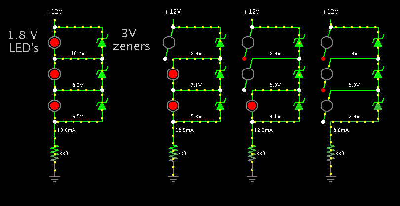
So I started by making a voltage divider to break the 12 volt into six segments of 2 volts each and was trying to figure a way to use the relay contacts and anything else short of a PLC to make this work.
My thoughts were to series the 2 volts in such a way that with all lights burning I would see the 12 volt total, but to somehow also parallel this so that if one relay opened due to loss of a light, I would see only 10 volts. And if two lights were shot, then I would see only 8 volts....etc.
This way I could determine how many lights were out at any given failure. But I have been banging my head against a wall trying to make this work. If it can be done using just relays and basic electronics, I would LOVE to know how to build it.
My thanks for any guidance or information that may help, or even if it is just knowing that I am trying the impossible.
John
I purchased and installed six DC current sensors and controlled each with one light. The sensors have a relay with a common, normally open contact and a normally closed contact. When current begins flowing (the lights are now burning) the relay changes states.
So I ran the battery feed to the GSM monitor through all the relays in a series circuit. So now if all lights are burning, I properly receive the voltage reading from the battery bank. But when a light is out (any light), the series circuit is broken and I get an alarm because of low voltage.
This is a big improvement. But I wanted to improve it even further by coming up with a design that would let me know not just that a light was out, but how many.
Sometimes they shoot just a single light, but other times they may shoot three or more. It would really help to know how critical my response should be and how many fixtures to take with me since the area is a long way to travel to.
So I started by making a voltage divider to break the 12 volt into six segments of 2 volts each and was trying to figure a way to use the relay contacts and anything else short of a PLC to make this work.
My thoughts were to series the 2 volts in such a way that with all lights burning I would see the 12 volt total, but to somehow also parallel this so that if one relay opened due to loss of a light, I would see only 10 volts. And if two lights were shot, then I would see only 8 volts....etc.
This way I could determine how many lights were out at any given failure. But I have been banging my head against a wall trying to make this work. If it can be done using just relays and basic electronics, I would LOVE to know how to build it.
My thanks for any guidance or information that may help, or even if it is just knowing that I am trying the impossible.
John
")