Continue to Site

Welcome to EDAboard.com

Welcome to our site! EDAboard.com is an international Electronics Discussion Forum focused on EDA software, circuits, schematics, books, theory, papers, asic, pld, 8051, DSP, Network, RF, Analog Design, PCB, Service Manuals... and a whole lot more! To participate you need to register. Registration is free. Click here to register now.

digital controlled negative current source

Status
Not open for further replies.

deniz88

Member level 2
Joined
Jul 28, 2009
Messages
47
Helped
0
Reputation
0
Reaction score
0
Trophy points
1,286
Location
germany
Activity points
1,703
Hi,

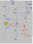
i want to make a digitally(FPGA) controlled negative current source. C1 capacitor is the load.
- i want that current change equally for every single bit , for istance
1110 = Ix
1101 = 2Ix
1100 = 3Ix...
but in my circuit current doesnt change propartional. i arrange resistor values to make it 2Ix but this time 3Ix doesnt happen.

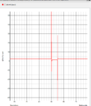
-another issue is, i am getting current peaks on fpga pin, is it because i connected it to negative current source(i had to do it to make sure Q7 base current flows)? I also tried Ref voltage to Q7 collector but after that i couldnt control current at all.
any suggestion to prevent these peaks, or any other sugestions to implement this circuit?

thanks a lot for helps.
 

Attachments

  • Negative Current Source.PNG
    Negative Current Source.PNG
    30.5 KB · Views: 128
  • fpga_pin_current.PNG
    fpga_pin_current.PNG
    38.4 KB · Views: 89

Hi,

it is not clear how the current source is controlled by the FPGA.

Please give more specific questions.
* What is your expected current range?
* What precision do you need?
* how much does the current deviate from the expected value?

I recommend to use an OPAMP constant current source circuit. It will be more easy to calculate and it will be more precise.

Klaus

- - - Updated - - -

added:

I expect that the 1 Ohm resistors are too low ohmic for your application.
There is a voltage drop of only one mV per mA.

Try to use 100 Ohms .. maybe this helps.
But this is just an assumption ... because of the missing informations.

Klaus
 

so sorry i posted wrong image.
current source.PNG

I would like to get current range between 10A-1A and it should be divided by 4bits.
it will be gate resistor, so 1 ohm should be in ordnung actually.

i guess transistor circuit is more faster and it is important at gate driver circuit.

any ideas how to eliminate current peaks?

- - - Updated - - -

thanks for your answer Klaus.
on this version i used ref voltage. on this case problem is my current range is not wide. i can have Imin around 4,6A. Any ideas how can i have bigger current range, min 1A max 8A for example? (Imax can be changed if i use higher value then 1k)
NCS.PNG

on the photo,
highest current when i connect only 1k and lowest current when i connect only 60 ohm. (i give 0 with FPGA to let current flow)

Thank you for helps.
 

Status
Not open for further replies.

Similar threads

Part and Inventory Search

Welcome to EDABoard.com

Sponsor

Back
Top