Continue to Site

Welcome to EDAboard.com

Welcome to our site! EDAboard.com is an international Electronics Discussion Forum focused on EDA software, circuits, schematics, books, theory, papers, asic, pld, 8051, DSP, Network, RF, Analog Design, PCB, Service Manuals... and a whole lot more! To participate you need to register. Registration is free. Click here to register now.

smps ferrite core getting too hot

Status
Not open for further replies.

Salvador12

Full Member level 4
Joined
Jul 16, 2014
Messages
201
Helped
3
Reputation
6
Reaction score
7
Trophy points
1,298
Activity points
3,862
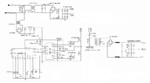
Hey , so I finally finished my smps which is a half bridge driving two IGBT's , all seems well , the IGBT's are barely warm etc but the transformer is getting hot even under longer periods of light loads.
The wires are not how they are simply warm and even could be that way because the core is giving off heat , the part that gets hot is the ferrite core , I wonder what causes this ?

the frequency is +-50kHz and the primary turns ratio is 11 turns. the wire is rather thick , haven't measured precisely but I think could be some 3 mm2.

the core is EPCOS ETD59, the material of ferrite is N87, with permeability of 5300nH.It has no airgap in the center pole.


the thing is everything seems to work, i'm getting my needed output voltages , also there isn't a lack of power , the IGBT's run only warm even with much higher loads as I have tried , up to 1.5kW.
the transformer core i causing me problems, what could it be ?
I suspect either too few or too many primary turns, maybe too many ?
 

you should check if your core is capable of delivering such power as you said..

you could give us all the design parameters in order to make some corrections if needed in the transformer design.
 

Reading the ferrite data sheet thoroughly should mostly answer your question, there are specifications of core losses versus frequency and induction.

There's also the EPCOS/TDK ferrite design tool that makes estimations of core and winding overtemperature for specific transformer designs.
 

Well the core dimensions are 59.8 x 31.2 x 22.1mm, and from simply looking at it it's rather large as compared to similar cores used in high power PC smps that go at 1kw or elsewhere.
I even anticipated the core getting warm/hot and made its support such that one of it's faces touches the common heatsink block for the whole smps.surely the heat transfer from a ferrite material to aluminum is less than good but it atleast does something.


as for the power , the core gets hot gradually and that seems to be the case both with light loads and higher ones.
I was running yesterday some two small speakers lightly and for some 20 mins and nevertheless it goes a bit hot to touch , definitely no more than some 100-200w of power through the transformer at that point.I assume there's something wrong with the turns count probably since the operating frequency is well within specified limits.

Would you please give the link to the design tool site ?
 

Attachments

  • 50khz-4n25-sg3525-smps-ir2110-smps-900w-70v-power-supply.png
    50khz-4n25-sg3525-smps-ir2110-smps-900w-70v-power-supply.png
    94.4 KB · Views: 157

I get Bmax of 190 mT for square wave with Vpk 150 V, Fsw = 50 kHz, n=11, a moderate value which shouldn't cause more than 25 degree temperature rise.
 

But what else ? I have 11 turns of some thick litz wire in the primary, yes it's a half bridge so the volts across primary is half mains rectified , and the frequency is 50kHz.
Well the voltage across primary is bit more than 150, because I have 230+ in the socket that gives me about 325v DC. so half that would be 162 v DC but I assume that doesn't play a big role as it's only a 10 volt difference.
 

it's far from a sophisticated procedure, but you can touch with your fingers in the reel to check if it is getting hot before the core, which could indicate the possibility that wire gauge is not properly sized.
 

you say its hot even on no load (the core).
So it sounds to me that the peak B is too high....check over you calcs again.
Take bsat as 0.3T
Look at isat = B.A.N/L

...Are your windings wrong such that you are going above 0.3T at all?

As you know, the core losses are from deltaB, the frequency, and the eddy current losses.

For me it sounds like somehow on light load you are going into saturation due to wrong turns.
 

@andre_teprom , what do you mean "the reel" ? before the core? I didn't understand.The whole core is getting hot but the windings are much cooler than the core if compared, rather strange as I usually have dealt with windings getting warm upon large loads.
Although I must say some Asian mains transformers that I have used in the past for driving some amps have gotten pretty warm in their cores too , and that's a big soft iron core and its factory made.

Well it's not exactly no load , I have two high frequency full bridge rectifiers on my secondary output each then has a capacitor filtering bank of 6 caps , 12 in total.It make me two identical outputs each being about 90-0-90 , each output drives two channels of 500w each.But that is the maximum AB class power output surely I wasn't running that I was running 2 channels with a light load , the other two were just sitting there eating some small idle current. also in the very smps secondary output I have 2x 15 Kohm resistors each across 90-90 output to limit the maximum idle voltage , without them I got some noise and also the max voltage exceeded my limits. well maybe now with the amplifier load attached such overvoltage would not rise anymore but just to be sure I left them there.

that's about my load.

I will make one more dummy load test to see how fast it gets warm with a huge dummy load attached like two water heaters or something else and then compare that with idle conditions.
 

@andre_teprom , what do you mean "the reel" ? before the core? I didn't understand.The whole core is getting hot but the windings are much cooler than the core if compared, rather strange as I usually have dealt with windings getting warm upon large loads.

I was considering the possibility that the transformer as a whole was being heated by the winding as a predominant cause; in such case when starting the switching operation would be possible to perceive a distinct difference in temperature of both parts, the ferrite surface and the winding reel. Anyway, You just answered this question above, which turn back the focus to the core.
 

yes the core is heating the windings rather than the windings heating the core , if the windings would get hot I would atleast know what to do.
 

Although this should not explain the overheating issue, in your schematic seems like missing the feedback sample of the output back to the IN pin. At least a dot is there indicating the likelihood that in original drawing a connection was there.
 

yes there were feedback for regulation but that regulation worked kind of crude and gave me voltage instability so I thought I don't need one and so i don't have it , the frequency is fixed as is the pulse width.
 

yes there were feedback for regulation but that regulation worked kind of crude and gave me voltage instability so I thought I don't need one and so i don't have it

Perhaps you not took the sample output from the appropriate point. I guess that the amount of capacitors in output, are giving you the requested stability at the price of saturating the core.
 

well i have 12x 160v/1000uF in the secondary filtering output.To give me some headroom after all it's a power amplifier that has to drive heavy loads at peak moments.But why would large capacitance at output be a problem for the transformer , I guess I just need to either adjust my turns ratio in the primary or try to regulate maybe the pulse width maybe that would do something ?

in the attached schematic there is a resistor 33 ohms between the pin 7 and pin 5 of the SG3525 square wave oscillator chip, I have included a manual rheostat in series with that 33r resistor so that I could change the duty cycle a bit , what do you think would that help some ?
 

It "should" work as others have already said.

the core is EPCOS ETD59, the material of ferrite is N87, with permeability of 5300nH.It has no airgap in the center pole.

Its a real long shot, but....

Are you sure its a genuine EPCOS core and not some kind of "Dragon Brand" compacted mud ? I have been stung several times myself by counterfeit components, and now I am becoming more than a bit paranoid.

Am having a tough time here right now with supposedly low noise transistors that I can hear two blocks away.
 

Well, i'm not sure but I got the core from RS components.Along with other components that I usually get from there , well this time i really want to think it's a mistake on my part but surely i have no such lab or equipment to tell you the inner structure of a ferrite.

Well as I said I have 11 turns of thick thick litz wore in the primary , running at 50kHz.If that in itself is wrong for this tyupe of ferrite described above I would be thankful if someone could point that out , since i'm not that fluent with formulas and maths to calculate all myself.I will do some more testing and see what the results bring.
 

etd59, 363mm^2, 310V/2, 50kHz, 11 turns on N87,

Bpk = 194mT max, at 50kHz, yes there will be some Trise in the core,

51.2 cm^3 0.2W per cc gives min core losses as : 5.12W approx, check your freq is actually 50kHz (10uS each way)

- - - Updated - - -

more primary turns would lower the core flux swing and hence core losses...
 

You can expect original manufacturer parts from RS or other catalog distributors.

There was a previous suggestion to check the actual transformer waveform with an oscilloscope, just in case.
 

Status
Not open for further replies.

Similar threads

Part and Inventory Search

Welcome to EDABoard.com

Sponsor

Back
Top