Continue to Site

Welcome to EDAboard.com

Welcome to our site! EDAboard.com is an international Electronics Discussion Forum focused on EDA software, circuits, schematics, books, theory, papers, asic, pld, 8051, DSP, Network, RF, Analog Design, PCB, Service Manuals... and a whole lot more! To participate you need to register. Registration is free. Click here to register now.

MOS Driver of Buck Converter for Charge Controller

Status
Not open for further replies.

M.Rehan

Full Member level 2
Joined
Feb 10, 2016
Messages
129
Helped
2
Reputation
66
Reaction score
33
Trophy points
28
Activity points
972
How to get drive signal for mos in given scenario
using bootstap circuit (ie using High Side MOS driver (IR 2110)) using Battery Supply(ragulated to 12V)
I know Bootstap circuit works but given scenario confused me

SPECs:
MOS driver used IR2110
Power to Mos driver:12 V regulated from same battery of 36V

Capture.PNG
 

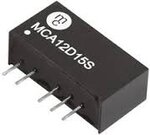
Easiest and least trouble prone way is probably to use an isolated 12v dc to 12v dc power supply.
These are available on e-bay for just a few dollars.
 

Attachments

  • Isolatedps.jpeg
    Isolatedps.jpeg
    3.6 KB · Views: 177

Its not a practical and economical :p

Charge controller in Market what they are using?
Like CM5024 solar cahrge controller
 

you couldnt even put the boot cap there,and a big resistor from it to gnd, so that the cap got charged up enough for you to get started.......because the batt voltage will put an end to it...so Warpspeeds solution looks good and ripe for use. Try to pick a module with as little capacitance as poss across its isolation barrier.
 
  • Like
Reactions: M.Rehan

    M.Rehan

    Points: 2
    Helpful Answer Positive Rating
The 12v to 12v isolated power module may look like overkill.
But its absolutely foolproof.

Any other way is fraught with unexpected problems that can be quite difficult to get around under all possible operating conditions.

Solar control systems can be particularly problematic around sunrise and sunset.
 
  • Like
Reactions: M.Rehan

    M.Rehan

    Points: 2
    Helpful Answer Positive Rating
If you are using Dc to DC converter in gate drives, be aware of common mode dV/dt....Recom do some modules that are designed for get drive use. I have used these on a large Inverter I designed a couple of years ago for s customer with excellent results.
 
  • Like
Reactions: M.Rehan

    M.Rehan

    Points: 2
    Helpful Answer Positive Rating
I have used these on a large Inverter I designed a couple of years ago.
Can You share further details and expereince about inverter and common mode dV/dt
 
  • Like
Reactions: treez

    T

    Points: 2
    Helpful Answer Positive Rating
Well the DC link voltage on this inverter was rated at over 700V, and the IGBTs I was using were quite quick so it would have been running at about 1400V/us. The key parameter (as has been mentioned elsewhere I think) is the inter boundary capacitance between the hot and cold side. The faster the dV/dt, the greater the capacitive current between the two sides. If this becomes excessive then this can lead to failure of the insulation, which obviously is a disaster. This was just a large AC drive.
 

Status
Not open for further replies.

Similar threads

Part and Inventory Search

Welcome to EDABoard.com

Sponsor

Back
Top