Continue to Site

Welcome to EDAboard.com

Welcome to our site! EDAboard.com is an international Electronics Discussion Forum focused on EDA software, circuits, schematics, books, theory, papers, asic, pld, 8051, DSP, Network, RF, Analog Design, PCB, Service Manuals... and a whole lot more! To participate you need to register. Registration is free. Click here to register now.

[SOLVED] Current transformer design and debugging

Status
Not open for further replies.

renga92

Member level 5
Joined
Jun 21, 2012
Messages
85
Helped
2
Reputation
4
Reaction score
2
Trophy points
1,288
Location
india
Activity points
2,084
Hi. I am trying to make an AC current transformer which can measure up to +/- 6A. At +/- 6A it should give an output of 1.2V. I simulated the circuit as given below in LTspice and it worked perfectly.

circuit_cur_trans.png

When implemented, it is not working as in simulation. Below is what I observed as waveform when probed at the output terminals.

IMG_20160429_152840959[1].jpg

Input to the current transformer (T3) is one of the outputs of h bridge as shown in the figure before.
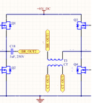
circuit_cur_trans_1.png

At no load condition[When the H bridge output is not connected to the isolation transformer], the current transformer output spikes when the MOSFET is triggered.
It should be 0 Amp across the current transformer but it is spiking as if there is a current across them.

The current transformer details are

Primary Inductance : 13.5 uH
Secondary Inductance : 7.25 mH
Switching frequency : 50Khz
Range : +/-6A

Could you help me figure out where the problem is ?

Thanks
 

Please clarify what you mean by the following:
At no load condition[When the H bridge output is not connected to the isolation transformer]
Also show actual pictures or drawings of the CT: including core type, number of turns, winding method, etc.

Another observation, the rectifier bridge should be substituted with a precision rectifier. You are losing the bottom 1.4 volts of the waveform.
 
I agree that the question is a bit confused, but the observed effect seems rather clear nevertheless. You see transformer interwinding capacitance which doesn't appear in your specified parameters
 
  • Like
Reactions: CataM

    CataM

    Points: 2
    Helpful Answer Positive Rating
The spikes are most likely the switching triggers for the mosfets. If your design is robust these spikes are of zero measure and will not affect the result.

Far more important is that you must keep the max current within the linear range of the B-H curve and the eddy loss must be small.

Did you try to bypass the spikes with a small capacitor to the ground?
 
What you can do is wind your primary and secondary on separate sections of a split section bobbin, to reduce capacitance between them.
 
The 100 ohm burden resistor should be placed after the bridge rectifier, not directly across the CT. That will eliminate all the lost voltage and linearity problems created by the diodes, provided the magnetics of the CT are up to the job.

Specifying inductance is not enough.
The magnetic core must not saturate with the total applied voltage, which will be 1.2 volts plus two diode drops.
Very high permeability ferrite is probably the most suitable material.
Diode drop can be significantly reduced by using shottky diodes, which is a definite step in the right direction.

Another trick you can try is placing a Faraday screen between primary and secondary. Usually the primary is only one turn, or at most a very few turns.
A short grounded copper sleeve passing through the CT is quite effective.
Then loop your primary turn(s) through the sleeve.

As you can buy suitable fully specified current transformers for under about five dollars, it hardly seems worth the trouble of designing your own and then trying to source a suitable magnetic core.
 
Wow thanks a lot for all your replies. This is my first current transformer built and so I didn’t know which parameters to share.
Regarding the current transformer parameters asked for :

  • Primary turns : 1
  • Secondary turns : 50
  • Core : T16 ferrite core
  • Winding method : clockwise winding [ I don’t know if I have answered it correctly]

@FvM : Could you please describe how the inter winding capacitance is calculated ?

@c_mitra : I did add a capacitor after the diode rectification. For this I changed value from 1nF to 10uF with no effect on the spike amplitude level. I have to check if the core is saturating at max current. If I am not wrong changing the current from min to max limit, correspondingly there should be a change in voltage on the secondary after rectification will tell if my current transformer is getting saturated or not.

@Treez : Based on what you said, I should not wind primary on top of secondary and both should be separately wound on the same core. Did I get it right ?

@Warpspeed : Thanks a lot for your suggestions. I have not even thought about these things. I will try to implement them and see if there is any change. I want to a small current transformer with custom specs for which I couldn’t find any online. Can you give me the places from where you can get custom current transformer done ?
 

Not sure what custom specs cannot be met by an off the shelf product ?

Anyhow, these are some CTs I bought off ebay a few weeks ago, and they work fine.
**broken link removed**

These have 100 turns, but with two primary turns you get the required 50:1 ratio.
These are rated for 20A, and with two turn primary would do 10A
Specified frequency response 2Khz to 200 Khz
For the low price, its simply not worth messing about.
 
@c_mitra : I did add a capacitor after the diode rectification. For this I changed value from 1nF to 10uF with no effect on the spike amplitude level. I have to check if the core is saturating at max current. If I am not wrong changing the current from min to max limit, correspondingly there should be a change in voltage on the secondary after rectification will tell if my current transformer is getting saturated or not.

Sorry I was not clear enough. I wanted you to bypass the input side of the transformer; use 10-100nF capacitors to ground (from both inputs of the CT). Also replace R1 with a 10-100nF capacitor.

Yes, you can plot the secondary voltage as a function of input current and see the linearity and decide whether the core is getting saturated (or not). Do not try to force the graph through zero and see the correlation coefficient.

- - - Updated - - -

Specified frequency response 2Khz to 200 Khz

This is certainly not intended for measuring current in the 50Hz range; but I certainly do not know the anatomy of the beast but they are most likely useful for pulse transformers for signaling use- just like an opto isolator. I do not know (but doubt) their linearity.
 

This is certainly not intended for measuring current in the 50Hz range; but I certainly do not know the anatomy of the beast but they are most likely useful for pulse transformers for signaling use- just like an opto isolator. I do not know (but doubt) their linearity.
You mentioned your switching frequency is 50 Khz, the core will be reset every 20uS, it never sees 50 Hz.

Linearity will be fine, until it saturates.
This one goes to 20 volts according to some specifications I found on the internet. Secondary inductance is quoted as 25mH so it must have a decent core.
 

You mentioned your switching frequency is 50 Khz, the core will be reset every 20uS, it never sees 50 Hz.

I blame it on ageing, I saw that but I also overlooked it- sorry for the goof up. He is trying to measure the current in a full-bridge setup.
 

Hi.
@Warpspeed : That ebay listing in not available in my country[India]. But still, it let me to see those options and I am planning to buy transformers available in my country. Custom application in the sense, I want the secondary voltage to 1.2V @ 5A rating instead of linear output of 5V for 5A. I think I will find a way around using a bunch of resistors.

@c_mitra : based on your comment, I see using off the shelf current transformer doesn't work for H bridge configuration ? Could you clarify on that ?
 

@c_mitra : based on your comment, I see using off the shelf current transformer doesn't work for H bridge configuration ? Could you clarify on that ?

No, I did not say or mean that. Somehow I mistakenly assumed that you are measuring current at the line frequency (50Hz).

Well, you can simply wind by hand a toroid and do some simple calculations. You can use the same transformer to plot the linearity graph. There is no black art in making a simple transformer.
 
When you have done your current sense transformer, do the following in LTspice to “see” the magnetising current peak. Click to show the primary current. Then show the secondary current but multiplied by NP/NS.
Then go “ADD TRACE” and subtract one from the other to see the magnetising current.

Then I(saturation) = B.A.N/L
 
I am planning to buy transformers available in my country. Custom application in the sense, I want the secondary voltage to 1.2V @ 5A rating instead of linear output of 5V for 5A. I think I will find a way around using a bunch of resistors.
It will probably be a lot easier to source a ready made transformer than source a suitable very high permiability ferrite toroidal core, and quite possibly cheaper as well.

The advantage of a commercial current transformer is you get some specifications to work with, and by juggling the primary turns and burden resistor its pretty easy to get exactly what you want in terms of output voltage per amp.

The 50 Hz power CTs usually only go to a volt or two before saturation, as they are almost always designed to drive a meter movement that may only need millivolts.

High frequency CTs are usually designed to give several volts at least, because that is what the usual application for them requires.
 
@Treez : Will give it a try. There is a lot you can do with LTspice !!!
@Warpspee : Yup. I am also coming to think that using ready made current transformer is a way to go. Iwas able to get some samples from coil craft part no : CS4050V-01L. Can you help me out if I can use this for my application ?
 

: CS4050V-01L. Can you help me out if I can use this for my application ?
That looks like an excellent choice.
Its rated 149V/uS so at 50 Khz (20uS max) should be good for 4.45 volts before saturation. Current rating and frequency response are more than sufficient.

At 6A there will be 120mA in the secondary, 1N4148 diodes are rated 200 mA so should be o/k unless you have a serious "overcurrent event".
I would prefer to use some 1A shottky diodes just for extra robustness and fault tolerance.

The ten ohm burden resistor needs to go after the bridge, not directly across the CT. That will greatly improve the linearity.
 
Hi Warpspeed. It has been long time and I finally got the samples from coilcraft. I am still using CS4100V-01L with Rt = 100 ohm and 1n4148 as diode, have put shottky diode on order. Can you please explain how you calculated the voltage at which it will go to saturation ?

I hope generally a voltage drop of 2V is good for 2 diodes and if I want an output of 1.2V DC then on the secondary of the current transformer I should be getting around 3.2V. Is my calculation correct ?
 

Can you please explain how you calculated the voltage at which it will go to saturation ?

The specification says 149v/uS maximum.
So if it was measuring 1uS wide pulses the secondary should be able reach 149 volts before saturation, but only for 1uS !

At 50Khz, one cycle is 20uS wide so the maximum pulse width it can ever see will be 20uS, usually a lot less, typically half that at 50% duty cycle.

At 20uS the secondary can sustain 149/20 = 7.45 volts.
But you need to subtract two diode drops from that.

Your required two volts will be well below that limit.
 
100 ohm burden is quite high (6V voltage drop at 6A primary current), but still far below saturation with 50 kHz current. For symmetrical square wave, 1/4 of the period (5 µs) has to be put into the volt-time product calculation.

If you don't mind a few percent error due to the magnetizing current, 1N148 bridge would be O.K.

CS4100V-01L has doubled volt-time product b.t.w.
 
Status
Not open for further replies.

Similar threads

Part and Inventory Search

Welcome to EDABoard.com

Sponsor

Back
Top