Continue to Site

Welcome to EDAboard.com

Welcome to our site! EDAboard.com is an international Electronics Discussion Forum focused on EDA software, circuits, schematics, books, theory, papers, asic, pld, 8051, DSP, Network, RF, Analog Design, PCB, Service Manuals... and a whole lot more! To participate you need to register. Registration is free. Click here to register now.

Isolated DC/DC design, input 9V...36V, output 15V 0.4A

Status
Not open for further replies.

urasinov

Newbie level 4
Joined
Nov 5, 2013
Messages
7
Helped
0
Reputation
0
Reaction score
0
Trophy points
1
Activity points
48
I need isolated DC/DC power supply, input 9V...36V, output 15V 0.4A.
Unfortunately, I have not experience in SMPS. I'm working mostly with MCU.
I need help to understand which topology is the best for my case.
End user wants to use this transformer https://katalog.we-online.de/pbs/datasheet/749196141.pdf. It has turns ratio 1:1
 

just 6w and single output...i dont know why you want to use a transformer with 6 coils on it.

ok ive just seen you need isolation....so then for you surely flyback is best i would have thought.

Try and find an off the shelf 1:1 coupled inductor with tight coupling, and ill give you a circuit. Come to think of it, your current is very low so maybe we can tolerate not-so-great coupling and just have a bigger rcd clamp for the flyback.
Try coillcraft, coiltronics, we-online etc etc for the 1:1

Come to think of it, cant you get a RECOM module that does that?..or similar.
 
Last edited by a moderator:

Very sound advice from treez.

It might be difficult finding a commercial power module with a wide enough input voltage range.
Most are nominally 12v or 24v input, and probably will not reach far enough.

These are not difficult to build and get going, but as treez suggests find a 1:1 transformer that will carry one amp average (required at 9v).
 

Your range of supply V is wide. With the right control IC for a flyback, you should be able to vary the frequency and duty cycle, to obtain output of 15V at .4A.

Simulation (based solely on theory):


Supply voltage is selectable by the switch. The switch was thrown halfway through the run.

As you can see, the waveforms need to be a few Amperes peak (because of the 'part-time' nature of the waveforms). Therefore the transformer needs to be rated for the peak amount.

Your transformer is rated for 0.9 A. It would be conceivable to use such a transformer, by running it from a full H-bridge, with a true AC waveform.
 

Plenty of choice of control IC, but you need to choose one that has an under voltage lock out no higher than 8v and a maximum supply voltage of at least 40v.

Neither is going to be a problem. but its something to look for when selecting a control chip.
 
This transformer is easy available for end user. That's why we want to use it.
I think I also can connect coils in series to increase inductance and create for example 1:2 transform ratio.
 

It might be difficult finding a commercial power module with a wide enough input voltage range.
Most are nominally 12v or 24v input, and probably will not reach far enough.
4:1 input range, specifically 9-36 V is a kind of industry standard. Tracopower TEN 6-2413WIN e.g. fits exactly the OP's specification.
 

If you want something easy and simple to use LT have the LT3999 (push-pull)

http://cds.linear.com/docs/en/datasheet/3999fa.pdf

You can download LTspice to simulate what you are doing to see if it suits, it all depends on exactly what you need, for me if you want to put something isolated together and not have to worry about isolated feedback compensation, and regulation is not so much of and issue over load transients something like that is ideal and would probably be ok with the transformer you mentioned from first glance.
 
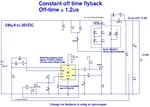
Here is a flyback that uses that transformer of yours.
It is a constant off time one, so no slope compensation was needed.
All 6 coils had to be used to get it done optimally, without going into saturation.

LTspice simulation is attached (ltspice is free)
-also the pdf schematic.
 

Attachments

  • flyback vin=9 to 36vdc, vout=15v,0.4A.pdf
    22.9 KB · Views: 127
  • flyback _vin=9-36vdc, vout=15v,0.04A.TXT
    7.7 KB · Views: 103
Thank a lot treez.
I am able to download txt file, but for pdf I see message
You have been banned for the following reason:
No reason was specified.
Date the ban will be lifted: Never
 

I dont understand the ban.

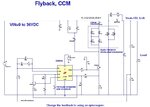
I have got you another version of the flyback here, it is this time in constant frequency mode (240khz), again i attach the schematic and the ltspice file.

- - - Updated - - -

Anyway, who is banned, me? or yourself?....i am not sure. You mean it wont let you download it?

- - - Updated - - -

Also, i attach the schematics as jpegs.....

- - - Updated - - -

We both managed to post messages, so neither of us can be banned...i think?
 

Attachments

  • flyback _vin=9-36vdc, vout=15v,_CONST FREQ.pdf
    22.8 KB · Views: 125
  • flyback _vin=9-36vdc, vout=15v,0.04A_CONST FREQ.TXT
    7.3 KB · Views: 86
  • Urasinov constant_off_time flyback schematic.jpg
    Urasinov constant_off_time flyback schematic.jpg
    109.6 KB · Views: 144
  • Urasinov constant frequency flyback schematic.jpg
    Urasinov constant frequency flyback schematic.jpg
    91.6 KB · Views: 208

Status
Not open for further replies.

Similar threads

Part and Inventory Search

Welcome to EDABoard.com

Sponsor

Back
Top