Continue to Site

Welcome to EDAboard.com

Welcome to our site! EDAboard.com is an international Electronics Discussion Forum focused on EDA software, circuits, schematics, books, theory, papers, asic, pld, 8051, DSP, Network, RF, Analog Design, PCB, Service Manuals... and a whole lot more! To participate you need to register. Registration is free. Click here to register now.

[???] Which MCU should I use to convert signal?

Status
Not open for further replies.

Alloy

Advanced Member level 4
Joined
Apr 3, 2016
Messages
116
Helped
0
Reputation
0
Reaction score
0
Trophy points
16
Activity points
1,003
Hello.
I want to read a 50Hz signal from AC transformer (only upper halfwave) and use it to generate square signal.

The output square signal should be preferrably at 5V level.

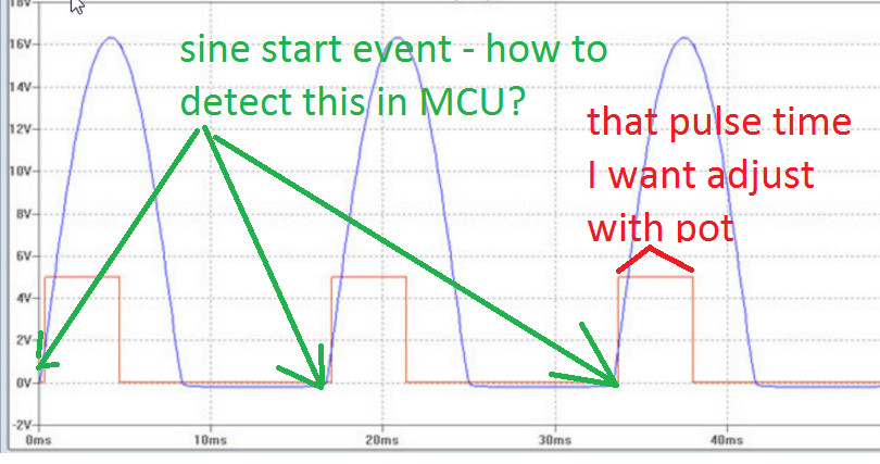
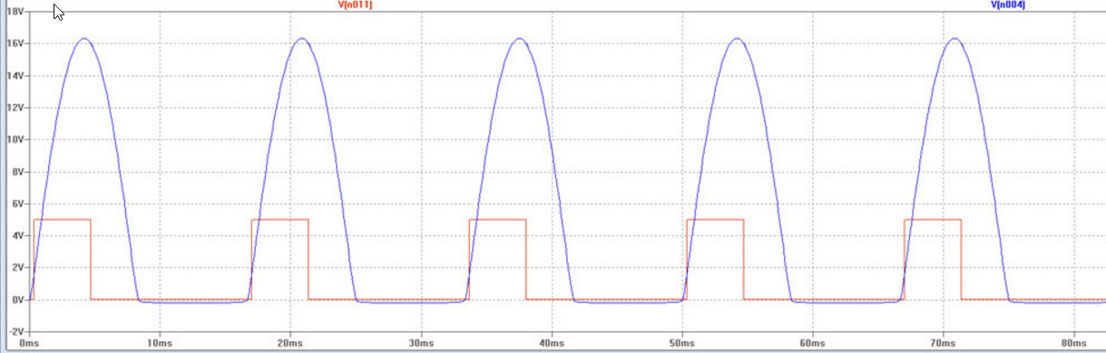
Please take a look at the picture:


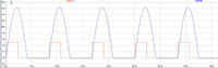
The blue signal is the signal that I want to read.
The red signal is the signal that I want to generate.
Both signal must be synchronized.

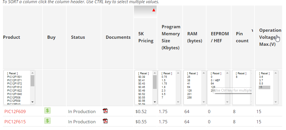
My question is: what cheapest and simplest MCU can I use for this purpose?
 

A rectifier diode to get the half wave and a zener diode to clamp the output.
If you don't want the output pulse to be the full period of the wave (although you say you want a square wave but only show a pulse), then something like a 555 can be used to set the pulse width.
If you want to include an MCU then you will probably need to up the parts count and the overall price.
Of source this answers the question that you asked directly. However I suspect that you may have asked the question for some solution that you have thought about for quite a different problem (https://xyproblem.info/). Perhaps if you tell us what you are wanting to achieve then we can help you.
Susan
 

A rectifier diode to get the half wave and a zener diode to clamp the output.
If you don't want the output pulse to be the full period of the wave (although you say you want a square wave but only show a pulse)

Well, exacly the pulse width could be set with a potentiometer

then something like a 555 can be used to set the pulse width.
No no, the double 555 stuff is where I started, but it had too many components and I want to fit a small case.

Of source this answers the question that you asked directly. However I suspect that you may have asked the question for some solution that you have thought about for quite a different problem (https://xyproblem.info/). Perhaps if you tell us what you are wanting to achieve then we can help you.
I need to generate shown waveform so I can drive other device.


So, I need:
- fast diode to cut off negative part of wave
- zener diode to clamp
- ADC pin to read sine wave
- second ADC for potentiometer?
- output pin to generate square

Is there any simple MCU with 2 ADC in DIP8 package?
 

Assuming you want to obtain a square wave from a 50Hz mains as you specified on initial post, you need just a bridge rectifier, so that will toogle the output at the same phase of the wave. If you need to trigger the change of the output at the same phase than input, namely at zero cross, you should use some analog comparator to detect at the smallest value you can.
 

Hi,

In post#4 you talk about "pulse width".
You want to adujst it? With the microcontroller?
***
In your picture the square wave goes low before the sine goes low. Do you need this? What timing?

Klaus
 

Hi,

In post#4 you talk about "pulse width".
You want to adujst it? With the microcontroller?
***
In your picture the square wave goes low before the sine goes low. Do you need this? What timing?

Klaus

Well, basically I need to only detect when the sine goes high. The puls width (time) can be adjusted by potentiomenter.

I can see imagine something like that:


My idea for pseudocode:
Code:
// forever in loop

// is sine rise detected?
if(sine start)
{
   PORTA = 1;
   delay = Read_From_Pot();
   Wait(delay);
   PORTA = 0;
}

now I can see two problems.
1. Which DIP8 MCU can I use? Is there any that works on 12V?
2. how to detect the sine start?
 

1. Which DIP8 MCU can I use? Is there any that works on 12V?
I've been around since the days of the original SSI TTL components (i.e. 54/74 series parts from TI) and they worked on 5V. I don't think I've ever seen digital logic part that was expected to run on a nominal voltage that was higher than 5V. I think you need to think about using a voltage regulator.
 

Hi,

Look for ATTINY13. I never used it, but it seems to fit.

Instead of ADC you coud use the analog comparator, this is much faster.
And it has built in PWM module, so it can generate more precise switch OFF timing.

Klaus
 

Which DIP8 MCU can I use?
E.g. PIC12F675. As said, plan 5V supply and a voltage regulator.

For the rising edge detection, a digital input should be sufficient, but you can also use PIC comparator block with adjustable threshold. Input voltage must be attenuated and/or clamped to 5V processor input range.
 

Hi,

It doesn't use a 12V supply as the OP seems to want.

Yes, I should have mentioned this: I don´t know any MCU that is able to work from 12V.

***
A dual RR comparator and some Rs and Cs and a D should work... without any microcontroller.

Klaus
 

That PIC suggestion was helpful, but I will not use the chip you guys said.
I've luckily found this: pic12hv615
According to Microchip Product Selector, this chip can run on up to 15V VCC!

https://www.microchip.com/ParamChartSearch/chart.aspx?branchID=1001


• Voltage range:
- PIC12F609/615: 2.0V to 5.5V
- PIC12HV609/615: 2.0V to user defined
maximum (see note)

What do you think about this chip? Can it really run on 12V? Is there any "basic connection" example?
 

What do you think about this chip? Can it really run on 12V? Is there any "basic connection" example?

Might work out for what you are doing. There are connection examples and a lot of calculations for the required pass resistor that is needed. See this app note.
 

The "HV" designation may be misleading. The processor implements an internal shunt regulator but the maximum voltage rating of all pins is similar to other 5V PIC devices. If shunt or series regulator is preferred depends on the application parameters, both can be easily implemented as external component, in case of the shunt regulator, a tightly tolerated Z-diode can serve the purpose.
 
  • Like
Reactions: Alloy

    Alloy

    Points: 2
    Helpful Answer Positive Rating
I have found example usage of PIC12HV615 .
**broken link removed**
Secondly, we
will assume that the circuit input voltage is 12V.


So, if I want PIC12HV615 to run at 12V I need a 200 ohm resistor?
 

Not necessarily 200 ohm. As previously said, the device provides a shunt regulator, the current through the resistor with minimal input voltage must be larger than the processor supply current plus current consumptions of driven peripherals.
 
  • Like
Reactions: Alloy

    Alloy

    Points: 2
    Helpful Answer Positive Rating
Not necessarily 200 ohm. As previously said, the device provides a shunt regulator, the current through the resistor with minimal input voltage must be larger than the processor supply current plus current consumptions of driven peripherals.

Thanks for clarification. But now, how can I calculate the current consumptions? I want to connect only a potentiometer and the MCP14E5 MOSFET driver

PIC12HV615 has 4 ADCs so I can connect up to 4 potentiometers?
A/D Converter:
- 10-bit resolution and 4 channels, samples
internal voltage references
.
 

Hi,

PIC12HV615 has 4 ADCs so I can connect up to 4 potentiometers?
Yes.
****

But I'm not sure if it makes sense. A microcontroller is a digital system with all the benefits of a digital system. (Calculations, low noise, low errors, no drifts, memory)
But a pot is an analog system. With it's drawbacks.

So a couple of pushbuttons, or an incremenatal encoder and the use of EEPROM may help to keep the benefits of a digital system.

Klaus
 

Hey
I decided to use PIC16F628A.
I am going to use ADC_Read(0).
I have such questions:
1. My PIC16F628A runs at 5V. The signal will be at around 15V or more AC. How should I protect it?
2.
I have such idea:

https://i.imgur.com/sjcEk3A.png

1N4148 (or any other) simple rectifier diode - is it's orientation correct?
The zener diode will protect PIC (cut off voltages larger than 5V)

Is this correct? Do I need also a resistor?

I will use ADC Input of PIC16F628A.

Any suggestions?

I only need to detect the upper sine part rise moment..
Thanks in advance!
 

Status
Not open for further replies.

Similar threads

Part and Inventory Search

Welcome to EDABoard.com

Sponsor

Back
Top