Welcome to our site! EDAboard.com is an international Electronics Discussion Forum focused on EDA software, circuits, schematics, books, theory, papers, asic, pld, 8051, DSP, Network, RF, Analog Design, PCB, Service Manuals... and a whole lot more! To participate you need to register. Registration is free. Click here to register now.
The error amp is only part of the overall open loop, as you know.
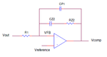
But yes you need to find the transfer function of it.....so your one above, it is Zfb/Zin....use complex numbers to work it out.
So you need the Power stage & modulator small signal trxfer function
Then you also need the error amplifier small signal transfer function.
Then multiply them
The take logs
Then plot Magnitude (db) vs frequency
And phase vs frequency.
Spot the gain and phase margin,
See if they are ok
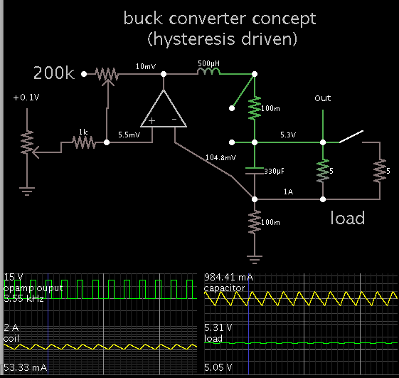
The buck converter is easy to regulate, compared to other smps. It is possible to make a regulated buck from an op amp (simulated, anyway).
Connect different nodes to the inverting input, to get different types of regulation (voltage, current). My simulation shows three positions where you can tap.
You want a certain amount of hysteresis. You don't want to delay the feedback signal for very long, or else you get undesired voltage swings at the output.
Similarly if gain is too high, then it can cause large output voltage swings.
here is something, also remember that your drawn error amp in top post drives its output till its inputs are equal in voltage...the circuit (smps) is set up so that when that happens (both opamp inputs same) you are in regulation.
Remember opamp with negative feedback..you expect to see the inputs the same voltage.
- - - Updated - - -
look at the attached ltspice sim of error amp regulating linear regulator..see how it works
- - - Updated - - -
it might be linear regulator but principle is same as error amp in smps, except in smps, the error amp output determines the duty cycle
This site uses cookies to help personalise content, tailor your experience and to keep you logged in if you register.
By continuing to use this site, you are consenting to our use of cookies.