Continue to Site

Welcome to EDAboard.com

Welcome to our site! EDAboard.com is an international Electronics Discussion Forum focused on EDA software, circuits, schematics, books, theory, papers, asic, pld, 8051, DSP, Network, RF, Analog Design, PCB, Service Manuals... and a whole lot more! To participate you need to register. Registration is free. Click here to register now.

Preamp 77.5Khz very narrow band

Status
Not open for further replies.

micman

Member level 1
Joined
Mar 27, 2002
Messages
40
Helped
0
Reputation
0
Reaction score
0
Trophy points
1,286
Activity points
207
Hi, I want receive dcf77 at 77.5Khz

But at 79Khz I have strong signal noise. I need a band pass filter of bandwith 100Hz max.

I think to use the classic circuit preamp with cascade jfet and in the drain the LC resonant circuit (L with troid toroids.info/T50-3.php ) .

example this circuit
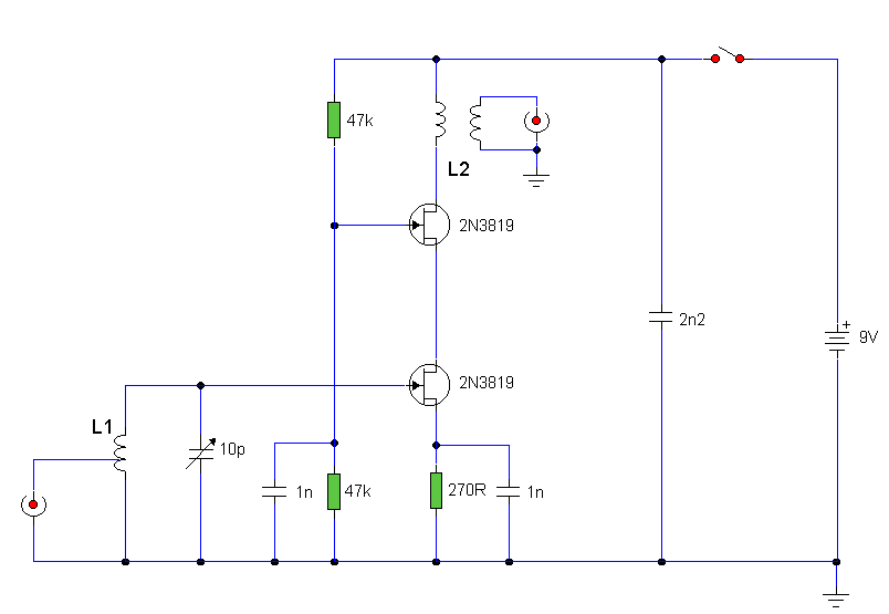
preamp88-108.gif


I select cascate jfet because I need very high impedence in output for LC resonant circuit for have High Q.

according to you,
Can I be able to have very narrow bandwidth preamp of 100Hz?
 

I believe you can get quartz/ceramic filters specifically for DCF, they would work far better. Intuitively, the LC ratio of L1 and =<10pf is not optimal, the inductor would have to be ~500mH. A better balance might be 1mH and ~4.2nF for the tuning.

Another alternative might be to add controlled positive feedback (Q multiplier) as that would increase the gain and narrow the bandwidth at the same time.

Brian.
 

Input filter Q is set by the inductor ESR which can't be recognized from the schematic. 100 Hz bandwidth @ 77.5 kHz means Q of 775 which is hard to achieve but not impossible.

There's no output resonator and thus the high output impedance feature useless so far. May be you forgot the capacitor, but the load impedance has to be considered in calculation.
 

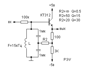
Can I use this circuit for Q multiplier?

n40.gif
 

Can I use this circuit for Q multiplier?
I fear, it's impossible in practice to achieve stable Q above 50 or 100 with this circuit. A promising Q multiplier candidate should have a higher initial Q. Requires a feedback circuit that doesn't load the resonator.
 

type a regenerative circuit?
 

For. 100 Hz BW, with direct conversion, you must choose 5 deg X cut Xtal probably with two stages depending on skirt rejection specs.

Cheaper is to use down conversion to a few kHz with IF filter Q of 30 max.

Most common is use Q of medium mu ferrite rod with Q up to 1000 if winding is done right with best ferrite. But not temperature stable, unless compensated a bit with PTC cap /w varactor/thermistor...
 

I do not think this is the way to go. A Q of 775 (loaded) would have an incredible insertion loss. Because you have to start off with a Q (unloaded) of much more then 775, then load it to extract any signal. The loss of a tuned circuit is (Qu -Ql)/Qu. So a Q unloaded of 1500,which is 775 loaded would have a 6 dB loss.
If you use a Q multiplier, this also multiplies the inband noise and would be susceptible to cross modulation.
If you have lots of signal, just use cascaded, loosely coupled tuned circuits. It is better to concentrate on the linearity of the RF amp amp. A pair of FETs in push pull, will cancel out their even harmonics (square law device) so should have excellent linearity.
Frank
 

A realistic approach apart from a crystal filter would use a higher order bandfilter with wider passband and higher stop band attenuation , e.g. 200 to 500 Hz bandwidth.
 

Quartz crystals are readily available for 77.5 Khz, so a practical home brew ladder crystal bandpass filter would be within the realms of possibility.

Another solution might be a purpose built Homodyne receiver.
Basically a mixer driven with 77.5 Khz local oscillator producing a zero frequency IF, followed by a 100 Hz active low pass filter.
Very easy to get a sharp cutoff at 100 Hz with a few op amps.
 

Micman, we are offering lots of possible solutions but perhaps the most important information that would help us is knowing what causes the interference at 79KHz. Many of the signals around that range are radiated from SMPS or low energy lighting and as such may themselves not be stable in frequency. If they are the source, there is a risk they will drift closer to DCF77 and impossible to completely isolate.

For interest, I can receive DCF77 and decode the time signal from here on the west coast of Wales. It is almost as strong here as the UK equivalent on 60KHz.

Brian.
 

A different approach to this would be a suitable loop antenna, rotated and then fixed in a position that nulls out the 79Khz interference.
 

FWIW my first design after graduation was a Doppler Nav. tracking device in 1975 using US Navy VLF, which had to work on a moving ice flow in the Beaufort Sea and send it's position to the 1st GOES satellite ( wind powered Automated weather station)

I wanted a BW of 1 Hz but compromised to a BW of 100 Hz with custom crystals (5° X cut)
Reception was in the low uV range with a 2m whip antenna from transmitters scattered around the world. It was 5 ch Rx from 15 to 23kHz that drew only 100mW.

These crystals worked from -40 to +40 easily and the ice flow moved almost 20km a day ...;) but ended up in Siberia.
 
Last edited:

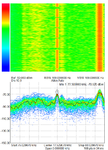
Send Capture image of signal:

The condition are:
-antenna ferrite with classic fet preap in balcony 2 meters above ground
-the pc (is on, for measuere signal) and my lab is to a distance of ~3 meters
dcf77.png
 

I test successful DCF77 receiver, I use mixer so42p , dds for Local Oscillator, opamo low pass filter and agc
 

When Q of LC BPF exceeds 100 or so, or < 1%, sensitivity to mechanical and thermal affects becomes significant and tolerance of components impossible.

You want 100 Hz BW in 77.5kHz or an effective Q of 775 which makes this impossible unless ovenized to < 1'C drift and rigid with vibration isolation and at least a 7th order filter with very accurate fixed temperature stable components and trimmer caps. Usually +ve tempco caps are used with natural -ve tempco copper chokes but are very uncommon.

As I said before the best solutions I used 40 yrs ago was 5 degree X-cut (E type) two-stage filter with a PLL with 1Hz bandwidth.
You can find tuning fork resonator filters now for $1 and with 2 stages and suitable coupling impedance design make a good front end filter with great temperature stability.

Once you get a carrier to noise ratio with sufficient suppression of out of band signals, you can use a PLL with a LPF to easily determine your BPF again using the same tuning fork component but now as a voltage controlled oscillator using varicaps.
 

thanks you for advice !!
 

Status
Not open for further replies.

Part and Inventory Search

Welcome to EDABoard.com

Sponsor

Back
Top