Continue to Site

Welcome to EDAboard.com

Welcome to our site! EDAboard.com is an international Electronics Discussion Forum focused on EDA software, circuits, schematics, books, theory, papers, asic, pld, 8051, DSP, Network, RF, Analog Design, PCB, Service Manuals... and a whole lot more! To participate you need to register. Registration is free. Click here to register now.

Ripple in rail voltage of H-Bridge

Status
Not open for further replies.

mrinalmani

Advanced Member level 1
Joined
Oct 7, 2011
Messages
463
Helped
60
Reputation
121
Reaction score
58
Trophy points
1,318
Location
Delhi, India
Activity points
5,285
Hi
I have a 12V full bridge operating at 100KHz, driving a transformer. The transformer output is rectified and filtered with a capacitor and then connected to a resistive load.
The 12V input to the bridge comes form a pair of 1.5 meter long copper cable, 4mm in diameter.
The rail voltage is very unstable. The pk-pk ripple is roughly 5V at 40A current, with 50uF ceramic capacitors connected across the rails.
Connecting additional 7000uF aluminium capacitor lowers the ripple to 3V pk-pk. The capacitor begins to heat up.
Adding another 14000uF lowers the ripple only by 0.5V. It appears that the value of ripple is more dependent on the NUMBER of capacitors in parallel rather than the value of the capacitors.
I am doubting the lead inductance to be the culprit.

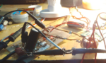
The figure shows the position of the capacitors marked in red.
(The connecting cables are just for illustration, and not of actual capacity)

How to stabilize the rail voltage of the bridge?
Bridge.png


Thank you
 

Had you measured the Vpp voltage drop at the 12v power supply ?
I mean, how much of that peak is due to the lack of regulation at the source…

I presume that the remote 12v comes from a battery, right ?
 

12V comes from a new 150AH battery and drop at the pattery terminals is no more than 100-200mV
 

1. You have connected with a cable that drops no more than 100-200mV

2. Power source is a new 150AH 12V battery

3. The ripple is 5V at 40A and 100kHz riding on the 12V input line??

4. You have put 50uF ceramic capacitors?? What is their impedance at the ripple frequency?

5. How much is the load at output? Does the load on the output has any effect on the ripple?

6. How long is the connection of the power transistors from the controller?
 

I think cable are too thin and may be a contact resistance problem.
Also, use few different type capacitors to cover wide frequency range.
 

The connecting cables are just for illustration
Same thing with the apparetly "invisible" capacitors.

I would prefer to see a photo with capacitors and power leads connected to the H-bridge. I wonder where capacitors should be connected in the shown output stage.
 

The rail voltage is very unstable. The pk-pk ripple is roughly 5V at 40A current

Perhaps if you completelly remove the varnish coating of the pad at where are solded these switching devices and cover up with a solder finish, this could reduce a few the drop voltage; that is a lot of current to be carried even in a large plane like that. Do you know what is the thickness of the PCB ?
 

The figure shows a 6800uF capacitor connected across the voltage rails.
The ESR of capacitor @ 100KHz is nearly 25mOhm
Cable resistance to DC is 7mOhm and to AC @ 200KHz is 40mOhm. (Ripples frequency is 200KHz)
Battery internal resistance is nearly 5mOhm
PCB(1oz) trace resistance of the rail is nearly 4mOhm (Hopefully)

When only a single electrolytic capacitor is connected with long leads, the leads get red hot.
When one capacitor with very short pair of leads is connected, connecting another with long (1") leads, doesn't improve the ripple.
 

Attachments

  • bridge2.PNG
    bridge2.PNG
    539.7 KB · Views: 92

Would be quite useful if you attach a picture showing the waveform of the ripple.
 

Double cable area and connect them in the middle of PCB trace (between transistors); put one capacitor bank on each bridge leg PCB points.
 

The observation that the capacitors are getting hot suggests that the ESR is too high- these capacitors are not suitable for 100kHz operation. Further the capacitors must be connected directly to the PCB and not using thin wires. I also do not think that 50uF ceramic capacitors are common. Instead of using a capacitor bank a capacitor inductor combination would be more suitable.
 

Problem is inductance and ESR of capacitors and capacitor leads.

You can take the design of PC processor power supply switchers as an example. They have a larger number of parallel connected low ESR bus capacitors.

Instead of using a capacitor bank a capacitor inductor combination would be more suitable.
An inductor can isolate the inverter ripple from the battery, but the ripple current must be sourced by the capacitors exclusively then. Thus it neither reduces the capacitor load nor the voltage ripple.

Ceramic capacitors aren't bad, but for a 100 kHz switcher, a simple hand calculation shows that 50 µF is still insufficient. Ceramic capacitors can be useful in combination with electrolytic to avoid high frequent ringing of the bus voltage.

I wonder what's the load current waveform. If it's almost a square wave, there shouldn't be much 200 kHz bus ripple. Or are you using pwm voltage regulation?
 
we don't know your schematic or transformer inductances etc, maybe you operating in real deep dcm..
Also, for pcb layout guidance, pse see attached.
I take it your MAX output power is around 540W?
What is vout and pout(max)?
 

Attachments

  • Basics of SMPS Layout _4.doc
    645.5 KB · Views: 54
The transformer leakage inductance referred to the 12V side is approx 150nH.
The High voltage side of the transformer is connected to a full bridge rectifier with a 68uF 450V capacitor as filter. The output voltage across the 450V capacitor is rather constant at 250V when loaded with 400W. I have not checked the input current waveform.

The transformer input waveform is a 100KHz square wave with 500ns dead band. Since the output uses a bridge rectifier, the ripple frequency is 2x the input frequency.

Keeping the 6800uF electrolytic capacitor connected and removing the ceramic capacitors (4uF) increases the ripple by as much as 2V
 

OK , but till your schem we do not see.....you are doing open loop by the sound of it, how do you limit vout when on no-load?
Also, it sounds like you are doing the fixed duty cycle of 90%.
What is the value of your output inductor?
from your leakage, I estimate that your primary inductance must be very low...I reckon you are way off into dcm mode.
What is Lpri and Lsec?
hOW ARE YOU DRIVING THE HI SIDE FETS (SOrry for capitals)
 

The transformer input waveform is a 100KHz square wave with 500ns dead band.
Keeping the 6800uF electrolytic capacitor connected and removing the ceramic capacitors (4uF) increases the ripple by as much as 2V
Sounds like talking about "200 kHz ripple" misses the point, I guess it should be better described as spikes with 200 kHz repetition frequency.
 
and I think we need the schem, as I cant see a sense resistor or current sense transformer anywhere,
 

It is also possible that the transformer is coming close to saturation and that may be source of all ills. Do you find that the core getting hot? When the core saturates, even for a moment, the results can be rather 'unpredictable'.
 

We need to see the waveforms. I'm assuming a significant part of the ripple you're seeing is emi from the bridge getting picked up by the probe. No amount of bulk bus capacitance will reduce that (though putting some good ceramic or film caps on the DC bus directly at the FET terminals may help).

Well the fact that your electrolytics are heating up means that at least some of the ripple is "real." You should look into getting polymer electrolytic or polymer tantalum capacitors, which can handle much more ripple than standard electrolytics.
 
Status
Not open for further replies.

Similar threads

Part and Inventory Search

Welcome to EDABoard.com

Sponsor

Back
Top