Continue to Site

Welcome to EDAboard.com

Welcome to our site! EDAboard.com is an international Electronics Discussion Forum focused on EDA software, circuits, schematics, books, theory, papers, asic, pld, 8051, DSP, Network, RF, Analog Design, PCB, Service Manuals... and a whole lot more! To participate you need to register. Registration is free. Click here to register now.

Variable power supply 0-80V 50A. High initial current

Status
Not open for further replies.

pcurrius

Newbie level 5
Joined
Feb 5, 2016
Messages
8
Helped
0
Reputation
0
Reaction score
0
Trophy points
1
Activity points
110
Hello Everyone!

I've a degree in Power Electronics and I'm trying to build a charger with variable output 0-80V and 0-50A aproximatelly. Now I'm stucked with high currents to charge up the large capacitor that I have on the output.

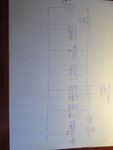
I have made and I attach the simple schematics of what I'm having right now.

I'm controlling the output voltage by a potenciometer from the controller circuit that controlls the firing angle of the SCR (Silicon Controlled Rectifier).

In order to solve this I have tried to insert a 2K 5W Resistor in Series before the rectifier but it charges correctly the first DC bus but it gets too hot when I attach the output capacitor of 10.000uf 400V. Also I tried to start with the resistor and after couple of seconds that the DC capacitor is little charged jump the resistor but the main 220Vac 16A switch opens.

I'm aware that the circuit needs a transformer and output coil but I would like to make it work without and then make an step further. Perhaps I'm wrong and it won't work without the transformer and the output coil.

Any recomendations to follow up and make this circuit more stable?

Many thanks in advance.
 

Attachments

  • 2016-02-05 11.05.56.jpg
    2016-02-05 11.05.56.jpg
    2 MB · Views: 114

The block diagram seems flawed, don't know if also the real circuit.

What's the purpose of a controlled SCR rectifier after a bridge rectifier with filter capacitor? How can the SCR ever turn off?

Would you mind to sketch a real schematic?

I'm aware that the circuit needs a transformer and output coil but I would like to make it work without
Without transformer can possibly work, but hardly without series inductor. There's a number of recent threads where people tried the same and failed.
 

Let me attach a more specific diagram with the actual components and their references so we can better discuss if it's flawed or not. **broken link removed**

The controlled SCR purpose is to vary the value of the output Vrms value of the output Voltage, so we can go from 0-80Volts depending on the firing angle. SCR turns off when the firing angle is 0. By the way, the SCR already have snubbers they are not present in the circuit diagram.

OK to begin with I will add this output inductor to stabilize the current.
 

Please follow the simple steps:

1. Select the input AC supply voltage.

2. Roughly sketch the waveform after the full bridge rectifier.

3. Roughly estimate the firing angles needed for the desired voltage.

4. Describe the type of controller you are planning to use

5. All filtering must be done after the SCR, NOT BEFORE.

6. A load that needs 50A at 80V may not mind some ripple. Design your filter conservatively but be realistic. Use a PI filter?

7. You mention 220V AC at one place. 50A at 80V will roughly translate into 20A at the input.

8. What is the load you are using?
 

Hi,

there is no need for the "uncontrolled" bridge rectifier.
Just use the "controlled" rectifier with AC input.
(it´s more easy to control the SCRs without the uncontrolled rectifier)

You may need an inductor between controlled rectifier and capacitor.

For battery charging you need a voltage control loop as well as a current control loop.
I´d go for a microcontroller solution.

Klaus
 

Hello KlausST,

Actually that was my first step but I evolved to this circuit trying to solve the high inrush current for the DC capacitor bank. Empty capacitor is a shortcut seen from the AC, that's my main issue. How would you solve this?

That's right but with this configuration I still have the same problem of the high inrush current when I turn on the pot to first charge the capacitor, notice that's a big one. 200 / 400V 10.000uF. I will add the inductor but will this solve this high inrush current?

On the other side I'm agree for the microcontroller, would you recomend me some of them to be used for voltage and current control loop?
 

there is no need for the "uncontrolled" bridge rectifier.
More exactly, it prevents operation of the controlled rectifier, because the SCRs can't be turned off any more.
 
I think this is called a blood and thunder PSU. The output capacitor is just too large. If the pot gets set to 80 V output and the leads are taken off the 80V battery and put on a 12V battery the firework display should be impressive. Any leakage through the SCR bridge will charge the output capacitor to some very high and unknown voltage - more flash and bangs?
The SCR bridge only needs two SCRs,the other are ordinary diodes. You need a current limiting LF choke in series with the controlled bridge to limit the current into the capacitor. But you are still stuck with the basic physics of the ripple versus the inrush current. I think you need a controlled bridge that starts up with a very small conduction angle to charge the 400V reservoir capacitors slowly or a resistor with a timer to short it out. Then a HF converter to reduce the voltage with feed back to stabilise and current limit the output.
Frank
 
Hi,
...to solve the high inrush current for the DC capacitor bank...
If you talk about the capacitor bank after your uncontrolled bridge rectifier: This capacitor bank is not needed..

If you talk about your capacitor bank at the output: On power up just smoothly ramp up your phase angle to limit inrush current.

Klaus
 
In agreement with post #11, if this is a battery charger, then I've seen them with no output (smoothing) capacitor. Last I knew a battery can tolerate strong current pulses, when charging.

In a way it is convenient because the unfiltered sine peaks become narrower, and push less power into the battery, as battery voltage approaches the peak voltage. Therefore that might become an advantage.

I cannot be sure whether this idea suits your battery requirements.
 

I think this is called a blood and thunder PSU. The output capacitor is just too large. If the pot gets set to 80 V output and the leads are taken off the 80V battery and put on a 12V battery the firework display should be impressive. Any leakage through the SCR bridge will charge the output capacitor to some very high and unknown voltage - more flash and bangs?
The SCR bridge only needs two SCRs,the other are ordinary diodes. You need a current limiting LF choke in series with the controlled bridge to limit the current into the capacitor. But you are still stuck with the basic physics of the ripple versus the inrush current. I think you need a controlled bridge that starts up with a very small conduction angle to charge the 400V reservoir capacitors slowly or a resistor with a timer to short it out. Then a HF converter to reduce the voltage with feed back to stabilise and current limit the output.
Frank

Hello chuckey,

many thanks for your feedback it is very appreciated. Let me answer you step by step:

1- When you say that the capacitor is too large which capacity would be enough for the worst case scenario that would mean 80V and 60A aproximatelly ?
2- Considerations about security are the first so for one side the capacitor has a resistor in paral·lel so if no charge is present it discharges and the second is that once you disconect the battery a signal will be send to the microcontroller and until the output voltage is not 0 again it opens the main contactor.
3- I have seen documentation on a semi-controlled half bridge rectifier and you are right, there is no reason to use full bridge in this application.
4- I really need to understand why LF choke will limit the input current of the capacitor. Are you talking about power line choke? or output dc line choke? Can you give me references? I found this: https://katalog.we-online.de/pbs/datasheet/7446120047.pdf Also if the power coil I already have the Schaffer FN2030 16-06 EMI filter that already has a power coil inside.
5- My other main problem is what you have exactly said, the firing module RT 380M starts with a too big conduction angle and incredibly as it may be the minimum peak voltatge is 100V and 24 Vrms. That's specially why then the current is so high. I attach a screenshoot taken from the osclilloscope with the minimum conduct angle of the firing circuit. It starts from the backwards of the sinewave instead from the begining. 2014-04-05 14.14.32.jpg
6- Would you mean a transformer to step down the voltage? I thought about this to reduce the minimum output voltage
7- Yes I will use feedback voltage to an ADC input of the microcontroller and based on that change the firing angle.
8- I will use a shunt to another ADC input of the microcontroller but I don't know how to limit the current, changing firing angle as well?
 

This method will only work with a large choke immediately after the SCR's (only one set of 4 doing the Ac rectification and control) or you can put it in the AC side (less o/p at full power)

I presume the AC is from an isolating transformer for safety?

- - - Updated - - -

the firing angle must start at zero and slowly ramp up (~5 seconds) until the overall control takes over and limits the firing angle based on the maximum of either output voltage or current.

- - - Updated - - -

At no load the firing angle will be near zero.
 

the firing angle must start at zero and slowly ramp up (~5 seconds) until the overall control takes over and limits the firing angle based on the maximum of either output voltage or current.

If the SCR fires close to zero (0+) the full voltage is applied. We need to set the firing angle close to 180- (slightly less than 180; just before the zero crossing) and slowly decrease (NOT increase) so that higher voltages get through. Am I confused somehow?
 

Hi,

If you talk about the capacitor bank after your uncontrolled bridge rectifier: This capacitor bank is not needed..

If you talk about your capacitor bank at the output: On power up just smoothly ramp up your phase angle to limit inrush current.

Klaus

Hi Klaus,

Many thanks for this input. I was talking about the output capacitor but as I say in my following comment the minimum firing angle still already to big to slowly charge the capacitor and it blows the main fuse. Perhaps solution would be:

1- Another SCR with smaller starting angle?
2 - Another configuration where the starting angle is 0 and not 90º and backwards. As I have seen by the oscilloscope the angle starts at 90º and goes to 0 so it takes the last part of the sine wave and not the very first part. Do you understand what I mean?
3- Transformer after the full / half bridge so we step down the minimum initial voltage around 0 -2Volts and therefore the capacitor slowly charges. I only need a maximum voltage of 80V not 270 as I have now and also I want mains isolation.
4- Another solution?
 

Hi,

If you need isolation, then you need a transformer.

You may use a mains frequency transformer. Either primary or secondary controlled.

Or you decide to use switch mode supply.

Btw: phase angle controled solutions with this power are usually not allowet to operate on public mains.
But I've done a similar project for an industral (non public) mains grid. I think i still have a transformer in stock..

Klaus
 

Hello guys,

I have made some new test after all your inputs and I made some new progress but still stuck in something strange for me...

I came back to my original circuit with the full wave rectifier and adding an smaller capacitor on the output (DC - 400V 470uf) with this scenario I'm able to very slowly turn the pot and charge the capacitor without blowing the main switch off. The problem comes when the lowest voltatge that I'm capable of charging the capacitor is aroung 50V- 200V (as you can see by my oscilloscope pictures the lowest peak looks like to be 100V), so depending on my hand the initial peak changes. My concern is that I need to have a minimum value of 2-6Volts and maximum of, let's say, 120Volts.

How would this problem to be solved? I come back to my last questions:

1- Another SCR with smaller starting angle? Is there any? This are semikron module RT380MU
2 - Another configuration where the starting angle is 0 and not 90º and backwards. As I have seen by the oscilloscope the angle starts at 90º and goes to 0 so it takes the last part of the sine wave and not the very first part. Do you understand what I mean?
3- Transformer after the full / half bridge so we step down the minimum initial voltage around 0 -2Volts and therefore the capacitor slowly charges. I only need a maximum voltage of 80V not 270 as I have now and also I want mains isolation.
4- Another solution?
 

Hi,

Did you add a big choke to limit current? This also makes the voltagd lower.

Angle: I don't think it's the SCR that defines the starting angle, it should be the control loop.

In any case it should start near 180° and slowly goes back. In other words it starts with a very short conductive time and it increases.
I'm not sure about the terminology. When the firing is delayed for 170° (non conductive) isn't the firing angle (conductive) 10°?

Klaus
 

As per Klaus above, some people refer to the firing angle as the actual degrees of conduction, in classical text books, 180 degrees = 0 firing time.

So start at 180 and slowly go to smaller values - without a choke though all is in vain as the peak currents will be enormous and destroy the silicon eventually.
 
Status
Not open for further replies.

Similar threads

Part and Inventory Search

Welcome to EDABoard.com

Sponsor

Back
Top