Continue to Site

Welcome to EDAboard.com

Welcome to our site! EDAboard.com is an international Electronics Discussion Forum focused on EDA software, circuits, schematics, books, theory, papers, asic, pld, 8051, DSP, Network, RF, Analog Design, PCB, Service Manuals... and a whole lot more! To participate you need to register. Registration is free. Click here to register now.

Noise on the GND from oscillator

Status
Not open for further replies.

itayd100

Junior Member level 3
Joined
Jan 7, 2016
Messages
29
Helped
0
Reputation
0
Reaction score
0
Trophy points
1
Activity points
233
Hello,

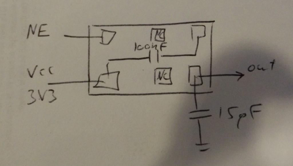
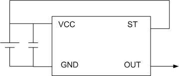
I connected an oscillator to 3V3 and ground. I'm getting the signal, but I'm also getting a lot of noise on the ground.

I tried to connect a diode between the GND to the GND of the oscillator but it still doesn't work.

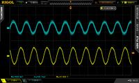
In the picture: the yellow is the output of the oscillator and the blue is the GND


Any suggestions?


Itay

https://www.farnell.com/datasheets/1995850.pdf
 

How did you measure the noise on the ground ?
Very probably you are seeing the radiated signal, received by the high impedance probe through the loop formed by the ground wire of the probe itself. Simply try to short the probe tip with its ground wire (left them unconnected with respect to your circuit) and try to come it near the oscillator; you should see roughly the same signal as in the picture you posted.
 
The weird thing is that I connected the probe to GND and the ground crocodile also to the GND and I got the signal around the zero. When I connect the probe to VCC and the crocodile to GND I got the same signal 3V higher. Yes, I have in the scope high impedance, but when I connected the probe and the crocodile together and tried to get closer to the signal I didn't see anything on the scope..

I'm trying to connect the (chip) oscillator --> buffer --> peak detector.
When I connect the peak detector to REAL wave generator I'm able to detect the peak, but when I'm using the chip I getting a sine signal, almost the same Vpp, in the peak detector.

(I'm new in analog circuits...)


Could you please post the schematic and a drawing where we can see how the two GNDs are physically placed and how they are connected with the rest of the circuit ?
 

You probably need some power supply decoupling to your oscillator.

Fit a suitable capacitor between 3V3 and ground right at the oscillator, then add a resistor or small choke in the supply line to the oscillator.

The capacitor will then supply the pulsing current demanded by the oscillator and the fluctuations in both ground and 3v3 source will both be diminished.
The size and type of capacitor depends on the operating frequency and supply current of your oscillator, but a 10nF chip capacitor and ferrite bead might be a good place to start at around 65 Mhz.
 
What is the load on the oscillator and where does its current
return? The two grounds are evidently distinct and you need
to have a good HF return path or you will drop voltage all
around "whatever the loop is".
 
Hey Tony,

This is my schematic(right up - GND):


What size of resistor or RFC would you recommend?

- - - Updated - - -

Hey,

What is a good HF return?
 

The blue line on the scope is having a lot of noise. That appears to be a power supply decoupling problem. You need a ceramic capacitor 0.1uF close to the circuit (connected to the PS ground).

What you mean by noise on the ground- where you are putting the test leads? Any electrical instrument can only measure potential difference and if your circuit has several grounds you need to tie them at a common point in a star fashion.

You put your scope leads (10X) in AC coupled and DC coupled mode and see the VCC line against the power supply ground. Then see the waveform at "out".
 

What is a good HF return?

As its only 3v3 I would first try it with one or two ferrite beads on the supply line.
It very often does not take much to be effective at higher frequencies.

The ideal situation is to mount everything on a common copper ground plane if possible.
 

As its only 3v3 I would first try it with one or two ferrite beads on the supply line.
It very often does not take much to be effective at higher frequencies.

The ideal situation is to mount everything on a common copper ground plane if possible.

Hey,
I attached a ferrite bead on the VCC and the GND lines and it doesn't seem to filter the signal.
 

You only filter the supply side, the ground should be direct and as short as as possible.
Try a small rf choke in the 3v3 line and a larger capacitor, say 1uF tantalum.
 

It seems very strange to me it's a problem of noise on Vcc. It is important you have an unique ground used for both GND pin (top right on you figure) and RF output. It seems you have two different grounds, instead. Could you please complete your drawing with the connections of the power supply and the two point between which you measured the noise you reported as "ground noise" ?

In any case I don't suggest to put a choke on the ground line.
 

What is the capacitor between Vcc and GND?

Replace with a 0.1uF SMD or ceramic. Not a high value tantalum or Aluminum.

Also make sure that PCB is clean before soldering the IC.
 

Status
Not open for further replies.

Similar threads

Part and Inventory Search

Welcome to EDABoard.com

Sponsor

Back
Top