Continue to Site

Welcome to EDAboard.com

Welcome to our site! EDAboard.com is an international Electronics Discussion Forum focused on EDA software, circuits, schematics, books, theory, papers, asic, pld, 8051, DSP, Network, RF, Analog Design, PCB, Service Manuals... and a whole lot more! To participate you need to register. Registration is free. Click here to register now.

Relay Chatter for Load Disconnection in Voltage Regulator

Status
Not open for further replies.

Unit00

Newbie level 3
Joined
Dec 14, 2015
Messages
4
Helped
0
Reputation
0
Reaction score
0
Trophy points
1
Activity points
46
Good day everyone.

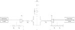
I've designed a voltage regulator, as shown in the second image below (Current Sensing.jpg). It is a series pass regulator with feedback. The load must be disconnected for excessive temperatures and load current above 1A. These measurements are obtained using a temperature sensor, and a current sensing resistor respectively.

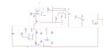
Connecting the relay as shown the first image below (Relay Setup.jpg), the load is disconnected for high temperatures just fine: a single click, and the load current is 0A.

However when the threshold for current cutoff is reached (1A), the load is not disconnected. Instead, the current drops to 0.56A, and the relay continuously chatters. Can anyone give me recommendations on how to fix this?
 

Attachments

  • Current Sensing.jpg
    Current Sensing.jpg
    97.4 KB · Views: 101
  • Relay Setup.jpg
    Relay Setup.jpg
    46.8 KB · Views: 101

Hi Unit00,

I would say- on a preliminary review of your circuit- since the temperature and current sense are symmetrical, the first thing I would check is if the relay opening operation interrupts the voltage/current conditions of the circuit, i.e. it's possible that the transient current generated from the relay opening causes a change in the current of the circuit, and therefore- closes the relay again, eventually causing the circuit to oscillate. I'd say- place a probe on the current sense circuit output and see if it "bounces".
 

Hi,

Funny, I'm trying to think through a similar design at present to understand regulators better by just designing a simple power supply roughly based on a regulator.

Sorry, I don't completely understand your schematics, my fault, so I ask if you are ORing the shutdown? - If one side says OK (temp) and the other says Shutdown (current) the regulator will struggle between off and on, maybe, hence relay chatter?

I hope to design in the OR so either event (over-temp or over-current) shutdown the "regulator" at the input side - rather than the output side - with a MOSFET as the enable device and input "gate" or "blocker", user-controlled and internally controlled by the OR gate events.

Mine is just a learning project. Sorry if I have misunderstood your design.
 

Hi Unit00,

I would say- on a preliminary review of your circuit- since the temperature and current sense are symmetrical, the first thing I would check is if the relay opening operation interrupts the voltage/current conditions of the circuit, i.e. it's possible that the transient current generated from the relay opening causes a change in the current of the circuit, and therefore- closes the relay again, eventually causing the circuit to oscillate. I'd say- place a probe on the current sense circuit output and see if it "bounces".

If I understand what you're saying, I don't think that would be the problem. In theory, if it was, then something similar would happen during the the temperature is high, but this doesn't happen.

I took some measurements today, and the circuit parameters seem normal during switching.Note that I've also included a flyback diode to minimize the effects of the voltage spike.

Hi,

Funny, I'm trying to think through a similar design at present to understand regulators better by just designing a simple power supply roughly based on a regulator.

Sorry, I don't completely understand your schematics, my fault, so I ask if you are ORing the shutdown? - If one side says OK (temp) and the other says Shutdown (current) the regulator will struggle between off and on, maybe, hence relay chatter?

I hope to design in the OR so either event (over-temp or over-current) shutdown the "regulator" at the input side - rather than the output side - with a MOSFET as the enable device and input "gate" or "blocker", user-controlled and internally controlled by the OR gate events.

Mine is just a learning project. Sorry if I have misunderstood your design.

Effectively, yes, the circuit is set up as an OR gate. If either the temperature or current is high, then the relay trips.

Considering what you said, that if one side is high and the other is low, then regulator would struggle between on and off, I don't think so. Since it is an OR gate, it would need at least one high input (i.e. Shutdown signal) to give a high output (load disconnection). That is, in this case, I think the relay is either OFF (load connected) or ON (load disconnected).

In your case, would the normally closed relay contacts just need to be connected between the input and the collector of the series pass control transistor?
 

Hi,

Thanks for explaining how your circuit operates, appreciated. I've only had a relay chatter when input voltage was not quite high enough to turn coil fully on (at first I thought relays were that noisy until it finally clicked on properly....) I'm not using a relay, just BJTs, a couple of MOSFETS and a few Op Amps, only been thinking it through for three days, so there are mistakes aplenty to iron out yet! I'm a bit lost as to how to design in over-voltage shutdown for input supply over-voltage, so it's back to copious reading tomorrow...

Stupid suggestion: would putting the relay under the transistors (image 1) make any difference, as in then no V+ to the relay except through NPN emitters, or gating relay through PNPs and using NPN as PNP drivers?

No problem, and point taken. I haven't tried increasing the voltage of the relay, since it works fine for temperature, but not current. But I'll try it still.

For the over-voltage protection, I would try something like a sampling the input voltage, then feeding that into a buffer, then use a comparator to switch on a transistor to allow current to flow through the relay coil, similar to above.

I didn't put the relay coil at the emitter since the output is at the collector (my reasoning). And I used NPN instead of PNP, because NPN switches faster than PNP. I wanted to minimize the delay between when there is over-current or high temperature, and when the load actually disconnects.
 

If the current goes too high, the circuit is broken. Then there is no current , the relay comes in again, the circuit current goes too high, the circuit is broken. . . .
You need another pair of contacts on the relay to latch it on once it has operated. And a reset button to unlatch it once the over current conditions have been cured.
Frank

In figure 1, I've configured the relay in such a way that it stays latched once it trips (normally open relay contacts across the transistor). It requires manually resetting via a normally closed push-button switch, in order to re-connect the load, which I also have in the circuit, as shown in Figure 1.
 

The problem is still the relay contacts, the circuit contacts open and cut the current before the latching contacts close. The gain of U4A is .3, removing R40 (10K) would increase its gain and drive the relay driver harder.
Can you use standard relay circuit drawings ?
Frank
 

Status
Not open for further replies.

Part and Inventory Search

Welcome to EDABoard.com

Sponsor

Back
Top