Continue to Site

Welcome to EDAboard.com

Welcome to our site! EDAboard.com is an international Electronics Discussion Forum focused on EDA software, circuits, schematics, books, theory, papers, asic, pld, 8051, DSP, Network, RF, Analog Design, PCB, Service Manuals... and a whole lot more! To participate you need to register. Registration is free. Click here to register now.

LtSpice transistor threshold calculation

Status
Not open for further replies.

Alper özel

Member level 1
Joined
Feb 28, 2015
Messages
40
Helped
0
Reputation
0
Reaction score
0
Trophy points
6
Location
Turkey / Scotland
Activity points
487
I have to use LtSpice to design an opAmp with pre determined MOS library: http://ptm.asu.edu/modelcard/2006/130nm_bulk.pm

However, I have no experience with LtSpice before and I really could not find what I want on internet so I am asking to you: How do I calculate the Vth so Mn*Cox in LtSpice?

I thought Vth0=0.378 was the threshold value of NMOS and Vth=-0.321 of PMOS according to the library text:

+vth0 = 0.3782 k1 = 0.4 k2 = 0.01 k3 = 0

+vth0 = -0.321 k1 = 0.4 k2 = -0.01 k3 = 0

However when I calculate the NMOS MnCox for I=10 u and 20 u in this configuration:
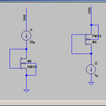
Screenshot from 2015-11-23 22:10:38.png

I get MnCox as 1.32m and 0.9m differently. So this calculation makes no sense. And what is the correct way to calculate it? Thanks.
 

Are you talking mobility (mu) times Cox?

If so you would want to make the device square
aspect ratio (W=L) so that factor becomes unity
in the equation I suspect you'd use, and well more
than the minimum L and minimum W (so delta_
effects are pretty much out of play. Something
like W=L=10um.

Your schematic shows nothing for geometry params.
This may be because LTSpice is aimed at discrete
transistors and SSI analog components, board level
and not IC design where varying geometry is the
main game. So properties, even if they exist on the
symbol, may not be chosen for display (you might
be able to alter this by instance properties, though).

Be sure about scale factors too (meters vs cm, units
vs 'u' after L & W values, etc.). If you see farads of
capacitance, you're probably doing it wrong ;)
 

Thanks for the reply. However, When I do that, Vgs becomes 0.374 and Vth0 is 0.378 according to model parameters. I still do not know how to calculate Mn*Cox. Do I have read it from model parameters?
 

Are you fitting Id=W/L*u0*Cox*(V-VT)^2? If so, jack
up the current (get away from VT) and see what that
looks like.
 

Yes I use that equation and more I jack up the current more I get Vgs. And it does not make any sense since I use the NMOS in diode configuration.
 

Sure, it makes sense. But it also is in a configuration
not quite like either VTlin or VTsat measurements, in
fact it is forced to straddle the border between the
two regions and so will not match either one's form
of equation very well.

An alternative I like, is to put Vgg=0, Vdd={sane
Vds-VT} and pull a negative current out the source.
Now you're definitely in saturation and can use that
equation.

Screenshot from 2015-11-24 23:28:30.png

Well, I think I did what yu suggest. 10u to 10u W/L ratio. I connect Vg to Gnd and pulled 1uA out of the source. The thing is which can you see in the pic above, Vgs becomes 373mV while model file says Vth0 is 378mV. I get stuck here. It is impossible to design an op amp without knowing Vt and therefore un*Cox.

I worked with cadence before and it was very fine. It was calculating Vt value and I then I was able to calculate unCox myself. But in ltspice, I am literally trying to find out the way to calculate Vt for weeks now. I really feel like a dumb.
 

You're only halfway there. Your 1uA at one square is
a "good enough" way to get VT. You'll sometimes still
see VT1UA along with VTLIN, VTSAT, ... in WAT test
data.

That is only one unknown in the equation. You need a
second Vgs and Ids, to extract the k' value. But at
least you got one knocked off.

So pull 50uA and 100uA out the source, same Vdg (and
close enough, Vds) and now 2 equations, 2 unknowns.
Or decompose that to its solution, delta-basis

ID1=K'(V1-VT)^2
ID2=K'(V2-VT)^2

ID2-ID1=K'((V2-VT)^2-(V1-VT)^2)

K'=(ID2-ID1)/((V2-VT)^2-(V1-VT)^2)

Bring your own electrical tox number and gate
area, 3.9*epp0 and badda bing, your mobility.

Or something like that.
 

Status
Not open for further replies.

Similar threads

Part and Inventory Search

Welcome to EDABoard.com

Sponsor

Back
Top