Continue to Site

Welcome to EDAboard.com

Welcome to our site! EDAboard.com is an international Electronics Discussion Forum focused on EDA software, circuits, schematics, books, theory, papers, asic, pld, 8051, DSP, Network, RF, Analog Design, PCB, Service Manuals... and a whole lot more! To participate you need to register. Registration is free. Click here to register now.

clock gating timing analysis with synthesized ICG cell

Status
Not open for further replies.

zhangljz

Member level 5
Joined
Oct 19, 2013
Messages
81
Helped
1
Reputation
2
Reaction score
1
Trophy points
8
Activity points
648
Hi guys,

I am using clock gating in cadence RTL compiler, but there is no ICG cell in the library. So I implemented an ICG cell with code, which is active high ICG cell
Code:
module ICG_posedge(
  input ck_in,
  input enable,
  input test,
  output ck_out  

);

reg en1;
wire tm_out, ck_inb;

assign tm_out = enable | test ;
assign ck_inb = ~ck_in;

always @(ck_inb, tm_out)
      if(ck_inb)
        en1 = tm_out;
              
assign ck_out = ck_in & en1;
endmodule


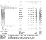
But after insertion of clock gating, it seems that rtl compiler take the ICG cell for timing borrow purpose, not for clock gating, like this:
to_clock_gated3.jpeg


I can not see the effect of the clock delay due to the ICG cell. In the picture, the clock of valid_event_buf_reg[10] is from an ICG cell (red cell), but in the timing report, the capture clock path only take clock uncertainty into account, no ICG delay.

to_clock_gated2.jpeg


I didn't use clock gating before, I don't how to make constrain on it, especially for the coded ICG cells.

Anybody can help.


Thank you
 

Why dont you simply use the condition to gate the output itself from RTL ?
...
if (reset ) out <= 1'b0;
if ( enable ) out <= in;
...

I think synthesis tool can implement a gator ( not ICG cell ) like AND, OR, etc... It supposed to reduce clock switching to FF/CP pins in the fanout.

For your question, Synthesis tool can not recognize your "module" is a dedicated clock gator. To make it a recognizable ICG to the tool, please check some command supported by it. Like in Synopsys, set_disable_clock_gating_check to FALSE as I remember.
 

Hi,

I made the module to be dedicated clock gating cell as it said on RTL compiler manual. And clock gating insertion works well. But the ICG cells seems to be transparent in timing report, because the flop valid_event_buf_reg[10] is clock gated, not directly driven by stop_HF, but in the report the capture clock still use stop_HF rather than the gated clock.
 

It is correct.

If you have a circuit like this:

CLKA --> clock gator A --> FF/CP

CLKA is gated sometime but not all the time. That why Tool can see "CLKA" propagating to FF/CP. Then, it calculates the slack base on CLKA's attributes.

You can see gated clock only if you define another generated clock after gator output.
 
  • Like
Reactions: 61ping

    61ping

    Points: 2
    Helpful Answer Positive Rating
Hi slutarius,

Thank you for your reply.

But will this cause violation? I mean the gator will cause some delay, but in the report the delay is not toke into account, because it directly use CLKA.

Especially in P&R ( I haven't been to this step), since the delay will be even larger, if the report still use the same strategy , it may cause some invisible violation due to this invisible delay.

will this be the case?
 

I am seeing "0" delay for launch clock in your pictures, so I assume you are doing timing report with "ideal clock" mode. All delay components along clock path will be skipped adn clock latency is 0.

I can not confirm this since clock path is not clear. Please turn your tool into propagated clock mode. I think you can know which logical path that your capture clock path goes through, and how much delay for each cell.
 
  • Like
Reactions: 61ping

    61ping

    Points: 2
    Helpful Answer Positive Rating
Status
Not open for further replies.

Part and Inventory Search

Welcome to EDABoard.com

Sponsor

Back
Top