Continue to Site

Welcome to EDAboard.com

Welcome to our site! EDAboard.com is an international Electronics Discussion Forum focused on EDA software, circuits, schematics, books, theory, papers, asic, pld, 8051, DSP, Network, RF, Analog Design, PCB, Service Manuals... and a whole lot more! To participate you need to register. Registration is free. Click here to register now.

[moved] led reacting to an mp3 module

Status
Not open for further replies.

gonadgranny

Member level 4
Joined
Feb 23, 2011
Messages
68
Helped
0
Reputation
0
Reaction score
0
Trophy points
1,286
Activity points
1,930
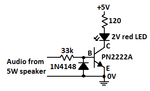
Hi all. I am currently working on a project which involves an mp3 module and i would like to get an led to react (in light intensity level) to the amplitude of the signal it generates. i am using a transistor to drive the led with the base connected to one of the mp3 modules speaker outputs which is amplified(enough to power a 5w speaker).the emitter is connected to a 5v source. i am aware that the led will only allow current through it in one direction so i am effectively only getting half of the waveform but it seems to work anyway. the problem i am having is that even when there is no sound playing the output generates about 2.5v so there is a constant glow on the led which makes the effect less impressive.
can anyone give advice on how to stop this? some way of getting the transistor to only react to voltages above a certain threshold for example?
ive tried connecting the transistor to the un-amplified source but it doesnt work as the voltage must be too low.
the transistor which i am using is the pn222a.
any help would be much appreciated.
thanks,
Dan.
 

Re: led reacting to an mp3 module

AC couple then use OP Amp and diode precision rectifier to control voltage controlled current sink or source. Using a log amp will compress the light range to match hearing but less impressive.

Search Google images for "Light organ schematic"
That was my 1st DIY project with 3 channels back in the 60's driving triac controlled lamps.

Now you can use color modulated Strings of LEDS with RGB over I2C bus on stripLEDs for each cooler features.
 

Re: led reacting to an mp3 module

You probably have a PN2222A which is an NPN transistor.
Its emitter should be at 0V, not +5V. The LED needs to be in series with a current-limiting resistor and they connect from the collector of the transistor to the positive supply voltage.
The base needs a series current limiting resistor.

When the base is 0V then the LED does not light.
5W into 8 ohms is a voltage swing of 9V peak which will damage the base when it goes negative because the maximum allowed reverse emitter-base voltage of a PN2222A and most other little transistors is 6V so you will need a diode connected in reverse from the base to 0V.
When the input to the series base resistor is about 0.7V then the LED will light dimly. Low levels will not light the LED.
When the input is a few volts then the LED will be bright.
When the input is at the maximum then the LED will be very bright.

Like this:
 

Attachments

  • transistor and LED.png
    transistor and LED.png
    5.4 KB · Views: 100

hi there. sorry for the late reply and thank you all for the replys. audioguru. ive tried your setup but whenever i connect the audio from the speaker output to ground it creates a short circuit. could you fathom what i might be doing wrong? thanks .
 

Hi,

whenever i connect the audio from the speaker output to ground it creates a short circuit.

I'd say this is the definition for a short circuit.. what else do you expect?
Why do you connect the audio output to GND?

Klaus
 

Maybe your speaker is fed from a bridged amplifier so that BOTH of the speaker terminals are driven from an amplifier. Then you connected one of the amplifier outputs to the ground of your LED driver circuit.
EDIT: I forgot. Sometimes one terminal of a speaker is connected to the positive power supply so that the speaker bootstraps the driver transistor of the amplifier. Maybe you connected the + terminal of the speaker to the ground of the LED driver circuit.

The LED driver ground should be connected to the amplifier's ground, not to the speaker. The 33k resistor should have a 0.22uF capacitor in series with the speaker output.
 
Last edited:
hey chaps. thanks again for the reply's. i was just trying to figure out why the chip is giving out a constant 2.5v. is it possible to generate audio with a chip which cant generate true AC and so instead uses the mid point of the voltage range as '0' and then creates the wave by increasing and decreasing the voltage around this reference point?
if this were the case then i am still confused as to why the led doesnt ever seem to glow dimmer than this 2.5v level(also tested with a multimeter and even when playing audio it still reads 2.5v).
im not sure whether this will make things any clearer for anyone of just make things more confusing but in the mean time i am going to try the setup using a different audio source. thanks again.

- - - Updated - - -

UPDATE
So ive just plugged another audio source(my computers audio output) into my multimeter and its dancing about all over the place(including positive and negative readings) so i think its safe to assume that my mp3 module uses a different method to create audio(quite possibly the one which i proposed above...)
so this would mean i would need another method to try and get the LED to react nicely.
If anyone has any ideas or thoughts that would be fantastic. thanks.
 

5mm LEDs have a saturated ESR of around 16 Ohms, so it will introduce some unless you buffer it from the supply or have a large power Amp ( not <<1W intended for ear buds). THey also are rated at -5Vr absolute max, so back to back with a power Op Amp that can drive the current you want is advised.

A Gain>x10 with diode compression feedback or a log Amp will give the dynamic range you expect since LEDs have a large threshold voltage from 2 to 3 V and your eyes and ears are logarithmic but linear current vs brightness characteristic of LEDs ... is obviously not logarithmic. 2~3 decades of voltage range would be what I would look for, but you may be satisfied with just blinkin' lights.
 
Last edited:

The output of an amplifier must have its voltage swing up and down. It can be from -2.5V to +2.5V then its idle voltage is 0V or it can be from 0V to 5V then its idle voltage is +2.5V and a coupling capacitor is used to pass the AC signal but block the DC.

Maybe your speaker is driven from a bridged amplifier that is two amplifiers. One amplifier drives one wire of the speaker and the other amplifier drives the other wire of the speaker to get double the voltage swing of a single amplifier. Then each amplifier has a DC output but they are the same so the speaker does not get DC across it. Use one of the outputs with a series coupling capacitor to block the DC.
 
Skinny guy, thanks very much for the reply but its kind of way above me! (i'll give it another read and see if it clicks)
Audio Guru, This sounds like the correct scenario. Ive read up about bridged amps and i think i get them. Would you be able to elaborate on what you mean by blocking the dc and why this would help me?
thanks again,
Danny
 

Audio Guru, This sounds like the correct scenario. Ive read up about bridged amps and i think i get them. Would you be able to elaborate on what you mean by blocking the dc and why this would help me?
If your amplifier is bridged then it uses an amplifier to drive each wire of a speaker and each wire has a DC voltage. You do not want a dC voltage across a speaker and you do not want the DC voltage to always turn on the LED driver transistor so you need a coupling capacitor to pass the AC signal but block the DC voltage.
 

Attachments

  • coupling to a bridged amplifier.png
    coupling to a bridged amplifier.png
    40 KB · Views: 127
Audioguru, could you confirm that the setup would be (in series) audio output > 33k resistor > 0.22uF capacitor > transistor base. thanks.
 

With a low impedance speaker output feeding a 0.22uF capacitor in series with a 33k resistor to the base of the transistor then the cutoff frequency (-3dB)will be about 21Hz.
Don't forget to add the diode at the based to ground.
 
Status
Not open for further replies.

Part and Inventory Search

Welcome to EDABoard.com

Sponsor

Back
Top