bmandl
Full Member level 4
Greetings!
I have a home project in which the microcontroller light dimmer is involved. I built custom PCB with AVR and triac controlled dimmer, but it doesn't work. When I was in testing phase, with protoboard circuit, everything worked perfectly, but now on PCB it does not. I made PCB exactly as I connected everything on protoboard. I used BT137 triac and MOC3021 as optocoupler with diac output. I meassured voltages in circuit with oscilloscope and I get about 1.5V drop on current limiting resistor for gate and about 1.5V drop on output diac, but I get almost full 220V drop on gate of triac. This is kind of wierd. Triac just won't open. I have zero cross detector and I am sending right signals to optocoupler input, so this is not the problem.
I don't understand why circuit worked, exactly the same one on protoboard, but it does not now on PCB. I already replaced triac in case it was fault, but it was not.
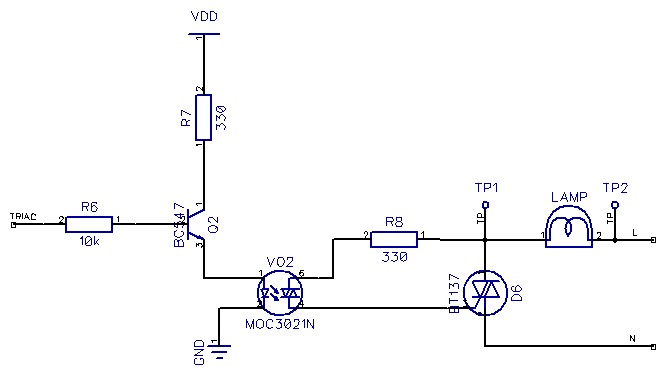
My trigger circuit:
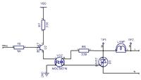
I have a home project in which the microcontroller light dimmer is involved. I built custom PCB with AVR and triac controlled dimmer, but it doesn't work. When I was in testing phase, with protoboard circuit, everything worked perfectly, but now on PCB it does not. I made PCB exactly as I connected everything on protoboard. I used BT137 triac and MOC3021 as optocoupler with diac output. I meassured voltages in circuit with oscilloscope and I get about 1.5V drop on current limiting resistor for gate and about 1.5V drop on output diac, but I get almost full 220V drop on gate of triac. This is kind of wierd. Triac just won't open. I have zero cross detector and I am sending right signals to optocoupler input, so this is not the problem.
I don't understand why circuit worked, exactly the same one on protoboard, but it does not now on PCB. I already replaced triac in case it was fault, but it was not.
My trigger circuit:
") ).
).