Continue to Site

Welcome to EDAboard.com

Welcome to our site! EDAboard.com is an international Electronics Discussion Forum focused on EDA software, circuits, schematics, books, theory, papers, asic, pld, 8051, DSP, Network, RF, Analog Design, PCB, Service Manuals... and a whole lot more! To participate you need to register. Registration is free. Click here to register now.

H Plane horn antenna with SIW

Status
Not open for further replies.

sara-s

Newbie level 5
Joined
Sep 24, 2015
Messages
8
Helped
0
Reputation
0
Reaction score
0
Trophy points
1
Activity points
50
Hi guys,

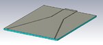
I am working on a h plane horn antenna.
First I calculate all dimensions that it needs, then I simulate it in the CST but my results are strange.
I have a good gain about 6 dB that it is fine in this level
I do not have any loss when I am checking the E-Fields
But my s11 is awful, it is almost zero, working like a resonator.
Do you have any idea why it is like that ?
I am suspicious to feeding and boundaries, because usually these two make your s11 so bad, I used a wave guide port for feeding and I choose open add space as boundaries.
Does anybody have any idea?
I attached the picture of my antenna.

Thanks
 

Attachments

  • Untitled.jpg
    Untitled.jpg
    25 KB · Views: 105

I would try to put blocking vias or wall on radiating edge and compare results. Also I would try to make SIW waveguide filter with microstrip feeding transition, after ensuring it works and have good S11 S21 I would cut one microstrip port and edit it with adding vias or walls to produce horn.
 

- - - Updated - - -

I would try to put blocking vias or wall on radiating edge and compare results. Also I would try to make SIW waveguide filter with microstrip feeding transition, after ensuring it works and have good S11 S21 I would cut one microstrip port and edit it with adding vias or walls to produce horn.


Thanks for your reply
I actually tried it already. I designed a horn antenna by PEC walls not SIW structure( like usual h plane horn antenna) with same dimensions. But my results were exactly same.
I really do not have any idea what is the problem.
Shall I just connect waveguide port to the substrate in wave guide or it should be connected to the metals too ?
what about the boundries? I used open add space, is the distance important ?
I appreciate it if you have any other ideas share it with me.

Thanks

- - - Updated - - -

I just change the boundaries from open add space to electric (Et=0) and just left the z direction for raddiation as an open add space and my results S11 is all under -10dB
but it does not make sense and this way is not right
 

Thanks for your reply

I designed my horn just with metal walls like a usual horn (without any SIW), but the result was same.not good at all.
then I changed the boundaries to electric(Et=0) in all directions and left the z direction as open add space, and the result was perfect all better than -10dB , but this way is not right, I should get the same results in open add space boundaries.
do you have any idea about it ?
 

I would try to put blocking vias or wall on radiating edge and compare results. Also I would try to make SIW waveguide filter with microstrip feeding transition, after ensuring it works and have good S11 S21 I would cut one microstrip port and edit it with adding vias or walls to produce horn.

I actually solved the problem with S11. But, Unfortunately I have another problem.
I optimized the waveguide size and then I got good result in s11. But this changes make my E-Fields zero. when I am checking the e-fields in CST it is all zero !!!!!!!
Do you have any idea about that?

Thanks
 

I think it is all related to excitation modes or simulation problems. I am not expert in both areas.
Mostly i saw papers on slot antennas using SIW. But interested in H Plane horn using SIW very much and will be happy to see if you got any good results.
 

Status
Not open for further replies.

Part and Inventory Search

Welcome to EDABoard.com

Sponsor

Back
Top