Continue to Site

Welcome to EDAboard.com

Welcome to our site! EDAboard.com is an international Electronics Discussion Forum focused on EDA software, circuits, schematics, books, theory, papers, asic, pld, 8051, DSP, Network, RF, Analog Design, PCB, Service Manuals... and a whole lot more! To participate you need to register. Registration is free. Click here to register now.

current sensing in pushpull topology

Status
Not open for further replies.

phenol

Junior Member level 1
Joined
Oct 4, 2012
Messages
17
Helped
1
Reputation
2
Reaction score
1
Trophy points
1,283
Activity points
1,471
Hi
I'm building a 12-440V/500W push-pull converter based on the UC2825A pwm controller.
The current sense xfrm (toroid)is now placed over the common junction of the two primaries, thus receiving unipolar pulses. The max duty cycle is ~93% so it has very short time to reset and fails to do so at heavy loads--the sensed current assumes negative slope. If i slide on a bigger core it works, but the reset pulses wildly exceed -500V. Even though they are about 300ns each, I don't feel comfortable running them close to other sensitive lines.
Plus, if i clamp the leakage inductance voltage spikes seen across the mosfets instead of allowing avalanche breakdown or even higher voltage spikes below the breakdown point, even the bigger core starts to act up. It appears that those overshoots help reset the current xfrm.
Now the question-- i need some ideas how to avoid saturation and a different placement of the xfrm where bipolar current can be sensed. I know i can pass the 'outer' legs of the power transformer thru the same current sense toroid in an antiparallel fashion, but it then becomes very convoluted as the primaries use 10 strands of wire each.
Maybe use two cores-one per leg- and then parallel them somehow...?
 

Two current transformers, combining the output through diodes.
 

if your sense current has neg slope then that is often because you have too much magnetising currnt flowing in the CST ...maybe because your turns ratio on CST is too small.
Can you not adjust turns ratio to bring duty cycle lower, then give you more reset time.....?....you shouldn't need to have a 500v reset voltage on the secondary of a CST.

Remember with CST, you just have to have, looking at the secondary side, that V.dt(on) = V.dt(off)..........as you can see, you don't need 500v for that.
Maybe your 'burden' resistor is too big, what is the max voltage you drop across burden resistor?

Also, I think full bridge smps is better for you..because you wont have to worry about the leakage energy, as it just goes back through the antiparallel diodes.....with the push pull, as you know, you need to quench out the magnetising energy, and the leakage energy, so a big snubber.
 

The burden resistor (after the diode) is 2 ohms. No significant improvement even with 1ohm. The cst has 100 turns.
I need to run the power xfrm at high duty cycles instead of increasing the turns ratio because otherwise the big difference between the average and peak voltage on the secondary side burns more power in the rcd snubber on the output

- - - Updated - - -

Full bridge is the next step, but I'll try to get that one going first.
I guess I'll follow FvM's suggestion and combine 2 cst, one per leg or split the cener tap junction and somehow tuck in the core there...
 

Why not cross over the two connections going into the current transformer, to drive it in a different direction each half cycle ?
A bridge rectifier on the output will then restore unipolar current measurement through the current measuring shunt.
This will then provide operation right through from zero to max duty cycle with core reset every half cycle.
 
  • Like
Reactions: FvM

    FvM

    Points: 2
    Helpful Answer Positive Rating
I bodged the current transformer onto the center tap, splitting it first and crossing over the two ends.
It's ugly alright, but works fine.
 

With cst location sorted out, I've got to focus on the output snubber now. Without any, there's some serious ringing exceeding 1kV, which blows the €€€€ out of the bridge rectifier, plus it superimposes ripple onto the cst output, rendering the primary side current control rather jerky. Now im using RCD or 2RCD snubber topologies, basically a diode, the anode of which is connected to the rectifier end of the output inductor, cathode to a resistor, the other end of which goes to the output, and a cap to gnd from the diode-resistor junction. With that in place the primary current waveform is free from ringing, except for the leading edge spike, which i eliminate by an external blanking circuit.
Anyway, what would be a viable output snubber topology in a converter like that? the output filter inductor is ~4mH, output voltage at D=93% and Vin=12V is 440V?
 
  • Like
Reactions: treez

    T

    Points: 2
    Helpful Answer Positive Rating
This is going to be a problem, the rather high voltage means a lot of watts probably need to be shed to damp that ringing.

One solution might be to split the 440v secondary winding into two 220v windings and use dual rectifiers and filters. That should at least halve the problem, and you may be able to get away without needing a snubber.
 
  • Like
Reactions: treez

    T

    Points: 2
    Helpful Answer Positive Rating
I'm going to see if soft recovery diodes (DSEP8-12A) yield any improvement over jellybean 5A 1000V parts, 5cents a pop. 1200V SiC diodes still bear hefty price tags...
 

Ok, so i swapped out the soft recovery diodes with C4D02120A SiC parts, which somewhat reduced secondary side ringing and overshoot, but it's still there and it needs snubbing for a nice and linear primary side current sensing.
some regenerative snubber suggestions are more than welcome!
 

following up on this, I went a different route and changed the topology to cascaded current fed push-pull converter, which automatically solved secondary side rectifier ringing (no inductor there). The controller is LM5041 configured for current mode operation. While it's running nicely, I can't get it to trip the second comparator threshold of 600mv and go in hiccup when the output is shorted. The first threshold of 500mv is reached and the buck stage pulse terminated rendering the whole thing a current source. It then dissipates tons of watts in the buck switches. I can't think of any other easy solution except disabling the controller once the mosfets temp exceeds some level...
 

Sorry I cant help you too much at this point with the current fed pushpull.
I thought current fed push-pull was for high vin, low vout useage, because it means you don't have an inductor in the high output current.
For your situation, sorry to give my 10c ,I would use dual interleaved boost followed by LLC, or full bridge...say boost up to 60v with the dual driver from Fairchild or linear or texas....then 60 to 440 with the llc or fullBridge......or maybe just use a single boost up front
 

For snubbing I generally start with the primary side. Have you tried putting any RC or RCD networks there? How is your transformer? Hand made?

following up on this, I went a different route and changed the topology to cascaded current fed push-pull converter, which automatically solved secondary side rectifier ringing (no inductor there). The controller is LM5041 configured for current mode operation. While it's running nicely, I can't get it to trip the second comparator threshold of 600mv and go in hiccup when the output is shorted. The first threshold of 500mv is reached and the buck stage pulse terminated rendering the whole thing a current source. It then dissipates tons of watts in the buck switches. I can't think of any other easy solution except disabling the controller once the mosfets temp exceeds some level...
Are you still sensing current at the transformer CT? The datasheet shows it at the buck input. Do you actually see CS rise to 0.6V? If not then that means the controller is doing its job as described. If you want that upper threshold to trip when the output shorts, then the inductance in that path (including the buck inductor and the transformer leakage) must be low. And the bandwidth of the CS signal must be high.
 

I had secondary side snubbing issues with the conventional push-pull causing severe ringing across the bridge rectifier diodes. Thus, i was compelled to go with 1200V devices, which is actually why i picked the current-fed push-pull. There is no secondary side inductor, no ringing and buck stage preregulation and i can now use 600V diodes.
The prototype transformer is indeed hand-made. Winding stackup is like so: 1 layer 1/2 secondary, primary-center tap-primary, 1 layer 1/2 secondary. The primary is copper foil covering the entire width of the former.
There isnt really too much overshoot across the push-pull transistors that can't be snubbed with RCD snubbers, which is what i actually did.
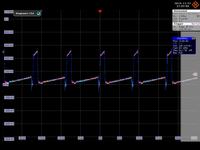
I am sensing the buck input current as per the datasheet. It terminates the buck gates drive as soon as it exceeds 0.5v and so it never reaches the hiccup level of 0.6V. The buck inductor is 1.5uH wound on a large kool-mu toroid. There is absolutely no filtering on the cs pin, im relying on the internal leading edge blanking. The image below shows the situation on the cs pin with the output shorted. There is also slope compensation visible in the picture. The inductor current looks trapezoidal with no signs of saturation, which would have tripped the 0.6V threshold


I am fine with this, but i'll have to eventually disable the driver somehow if the short persists to protect devices from overheating
 

yes, good idea, just let it start up, then when the oputput voltage gets into regulation, "arm" the short circuit detector to shut down the ic....the short circuit detector need just be a comparator sensing the output voltage, and tripping if it goes below x volts
 

yes, that's one of the options i am considering. another one could be a thermistor on the buck stage mosfets, comparator and hysteretic over temperature hiccup in the event of short on the output or any other fault. i never actually shorted the output with full the 440V on the 470uF cap there and i never would.
 

Ok, so I added a ptc thermistor cutoff circuit which stops the pwm controller when things get hot.
Now I'm running again into CS transformer reset woes (as with the earlier pushpull design described earlier, but now i have no way of doing bipolar current sensing)at max duty cycle operation. the buck stage switching period is 16us with only 250-300ns available for cst reset at max duty cycle. The diode on the cst secondary is BYV26c, a reasonably fast part with soft recovery properties. Needless to say, reverse diode voltage shoots hundreds of volts as the cst attempts to reset itself and within 2 cycles it saturates and droops. I tried a large assortment of other Si fast diodes, anything from 200mA to 10A, no joy. Then I whacked in C3D1P7060Q, a small 3mmx3mm SiC diode. This essentially allowed the cst to reset even within the available 250ns and maintain positive slope. it seems that reverse recovery current in conventional si diodes hampers cst reset.
 

Status
Not open for further replies.

Part and Inventory Search

Welcome to EDABoard.com

Sponsor

Back
Top