Arrowspace
Banned
I am trying to send serial data output from single pin using PIC18f4550
what logic I have to implement if I want to send 01001010
using RB0 pin.
My serial port is busy with some other function.
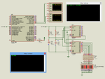
I am using serial to parallel connected at RB0 pin of microcontorller
I have used timer to generate clock, but not getting how to transmit data using single pin.
what logic I have to implement if I want to send 01001010
using RB0 pin.
My serial port is busy with some other function.
I am using serial to parallel connected at RB0 pin of microcontorller
I have used timer to generate clock, but not getting how to transmit data using single pin.