Continue to Site

Welcome to EDAboard.com

Welcome to our site! EDAboard.com is an international Electronics Discussion Forum focused on EDA software, circuits, schematics, books, theory, papers, asic, pld, 8051, DSP, Network, RF, Analog Design, PCB, Service Manuals... and a whole lot more! To participate you need to register. Registration is free. Click here to register now.

Current sense transformers on ETD type bobbins?

Status
Not open for further replies.
T

treez

Guest
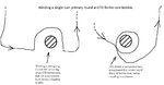
Would you agree that it is too risky to get SMPS current sense transformers wound onto ETD type bobbins? After all, if the winders forget to actually cross the primary wire back over itself then the primary may have zero coupling with the secondary, as the attached shows.
As you know, this can't happen with toroid cores since the winding is taken through the centre of the toroid, and therefore, there is always a completed turn of primary coupling up with the secondary.
So do you agree that its best not to wind current sense transformers on ETD type bobbins?

In the attachement, the winder has wound the primary round the bobbin in both cases, but in one picture, it doesn't end up forming a whole turn round the bobbin, which is bad.
 

Attachments

  • CST.jpg
    CST.jpg
    102.9 KB · Views: 161

Would you buy a toroid transformer from a guy who is obviously in the wrong business?
 
  • Like
Reactions: treez

    T

    Points: 2
    Helpful Answer Positive Rating
A half turn can be used to intentionally make a leakage inductance in series with the transformer ( which certainly is not the case ), but even considering this case, it may not be suitable in the matter of EMI susceptibility.
 

Would you buy a toroid transformer from a guy who is obviously in the wrong business?
thanks, at least with the toroid it is harder to go wrong..i mean, as long as the primary goes through the toroid "hole", then its fine.
In the above, the winder has gone round the bobbin and terminated seemingly correctly, but the picture on the left is totally wrong. I think the picture on the left could easily happen.
 

After looking again at your sketches, I wonder which configuration is actually meaned with the left one?

CST1.JPG
 

The above is a single turn with the rest of the turn completed by the external ckt...
 

Practically even the least professional guy is not expected to do this mistake , it`s different story if we think of a cobbler starting a salon though ... :)
 
  • Like
Reactions: treez

    T

    Points: 2
    Helpful Answer Positive Rating
Yes, Wuerth electronics has the same kind of current transformers. But it's not clear yet if treez might have meaned something different.
 
  • Like
Reactions: treez

    T

    Points: 2
    Helpful Answer Positive Rating
Actually, there are commercial products that employ exactly that winding configuration, with good results:
thanks, but the datasheet doesn't indicate how they wind the primary, ie as per the left hand diagram, or the right hand diagram (in the top post). I bet they wind it as per the right hand side diagram.

- - - Updated - - -


Right, Thanks To FvM, ive just noticed FvM's drawing shows the side posts too...
 
Last edited by a moderator:

And FVMs drawing is electrically identical to a toroid with a wire passed thru the center...

Seriously, use a proper winding company, specify what you want and they will be pretty good about delivering it.

Why are you doing custom CTs anyway? The things are an off the shelf part for almost any reasonable configuration.
You have way bigger headaches in designing a big switcher then sweating somebody supplying a magnetic component that totally fails to meet spec.

Regards, Dan.
 
  • Like
Reactions: treez

    T

    Points: 2
    Helpful Answer Positive Rating
off the shelf CST's have too much primary inductance, and this will add to the 6uH of resonant inductance that we have in our LLC converter, and significantly mess up the LrCr resonant frequency. We need something with <400nH of primary inductance. All the off the shelf ones have far more than this.
We have 25amps rms of current in the Lr inductor. (also in the CST primary)
 

[Moved]Leakage inductance in Current sense transformer will be too high?

Hello,
We are using current sense transformers to sense current in our 7.4Kw interleaved PFC boost converter. (as in page 1 of the UCC28070 datasheet, below).

As you can see, the current sense transformer (CST) primary needs to be in the drain connection of the power FET(s), hardly ideal, since the leakage inductance from the primary of the CST ( albeit small) will tend to cause overvoltage ringing with the FET DS capacitance.

The problem with CST’s with a single turn primary, is that the single turn is usually completed by the external circuit (on the PCB) connected to the primary, and this circuit may extend some distance away from the torroid core of the CST. This means that the coupling of the single turn with the secondary will be less.
(IE, the primary turn of the CST is not “completed” within the “package” of the CST itself, and this is a large disadvantage, meaning a large leakage term will occur)


On page 356 of Snellings book (below), we see how the equation for leakage inductance tells that the leakage inductance increases as does the “mean length of the turn”. This is bad, because the length of the primary turn with a CST could be quite large.

E.C Snellings book, “soft ferrites, properties & applications”…………..
https://archive.org/stream/SNELLING__SOFT-FERRITES__1969#page/n373/mode/1up

Therefore, do you recommend physically winding the primary of the CST, such that the primary fully encircles the torroid core, within the CST package?
Then one should measure the leakage inductance, by for example, shorting the primary, and then measuring the inductance seen in the secondary. This value, divided by 10000 (considering a 100:1 CST) will be the leakage inductance?

UCC28070 Interleaved boost PFC controller.
https://www.ti.com/lit/ds/symlink/ucc28070.pdf
 
Last edited by a moderator:

Thing is, if the loop area is large, you are probably stuffed whatever CT you use, high power switcher layout is ALL about minimizing current loop areas.

I recommend picking (or specifying) a part that meets the required spec and not worrying too much about how the part manufacturer gets there as long as they do meet spec.
The nice thing about this approach is that you as the design engineer do not need to be a magnetics design and magnetics DFM guru (Transformer companies have those guys), you can treat the details of core behavior and winding methods the same way you treat the silicon lattice constants when you pick a chip (Interesting, but fundamentally somebody elses problem).

Regards, Dan.
 

thanks, but so that we can check what leakage inductance that we end up with (we need to know this ), would you rate the following method...

-one should measure the leakage inductance of a 100:1 CST, by for example, shorting the primary, and then measuring the inductance seen in the secondary. This value, divided by 10000 (considering a 100:1 CST) will be the leakage inductance as seen from the primary?

The winders may not appreciate that we really need to wind for low leakage inductance, they may just do it their "standard" way, and we end up with lots of leakage inductance.
 

To derive the leakage inductance of a current transformer, you'll either perform 3D AC magnetic simulation, or empirical measurements.

Snelling's leakage inductance formulas are almost uselesss for a single turn winding of a conventional transformer and even more for a toroid core with an asymmetrical single turn.

In the symmetrical case, there's about no core flux generated for a shorted transformer, which means that the leakage inductance doesn't change much when you remove the core, it's essentially the leakage inductance of an air core transformer. Things are different in the asymmetrical case, you'll see that the core increases the leakage inductance of a toroid core with a single turn at one side.

Finally, it doesn't make much sense to worry about current transformer leakage inductance without looking at total wiring inductance. Typically it's only a minor contribution.

On the other hand, if you design a low inductance inverter layout, you should analyze the current sensor as its integral part, including the respective current return path.
 

thanks, by "asymmetrical", you mean that the turns are bunched up on one side of the torroid ring, rather than spread evenly around it?
Also, could you confirm that a higher permeability torroid core for CST would not be likely to give less leakage inductance than a lower permeability one? ie, the pri/sec coupling factor would be just the same, for a similarly wound CST on a high and a low permeability core?
 

you mean that the turns are bunched up on one side of the torroid ring, rather than spread evenly around it?
Yes, I was particularly talking about a single primary turn.

the pri/sec coupling factor would be just the same, for a similarly wound CST on a high and a low permeability core?
In a first order, yes. In case of the asymmetrical winding geometry, a certain increase with higher µr core may be observed.
 

These posts have shown that its fine to get CST's wound on ETD or EFD type bobbins. Since this is so simple, and since CST's rated for35A+ of current are so rare in UK/Europe/USA, why does everybody not just do DIY CST's with ETD type bobbins?
 

there are a lot of good SMD CT's out there on smaller EE cores complete with high current (25A) single turn primaries commonly used in switch-mode, often with 500T sec's, for 50kHz - 200kHz.
 
  • Like
Reactions: treez

    T

    Points: 2
    Helpful Answer Positive Rating
Status
Not open for further replies.

Similar threads

Part and Inventory Search

Welcome to EDABoard.com

Sponsor

Back
Top