Continue to Site

Welcome to EDAboard.com

Welcome to our site! EDAboard.com is an international Electronics Discussion Forum focused on EDA software, circuits, schematics, books, theory, papers, asic, pld, 8051, DSP, Network, RF, Analog Design, PCB, Service Manuals... and a whole lot more! To participate you need to register. Registration is free. Click here to register now.

dspic33ep512mu814 ic getting over heated

Status
Not open for further replies.

raman00084

Full Member level 6
Joined
Nov 29, 2010
Messages
362
Helped
2
Reputation
4
Reaction score
2
Trophy points
1,298
Activity points
4,006
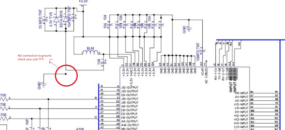
i bought 4 dspic33ep512mu814 from microchip direct. i designed the pcb as per microchip specifications if i solder the chip to the pcb the chip grtting over heated and burned all the 3 chips same issue next what i tried is i took the last chip and connected only the vss and vdd pins alone to 3.3v supply that ic also got burned kindly tel me what could be wrong i am using esd mate with eds protected soldering rod. kindly help


regards
kalyan.
 

I assume you've connected ALL of VDD, VSS, AVDD, AVSS, VUSB3V3 and the VCAP with a 10uF capacitor to their appropriate VDD or GND as indicated in the device datasheet?

If so, I suspect one of the VSS, AVSS or possibly the -VREF maybe either inadvertently switched or shorted to VDD somewhere on your PCB.

I would test continuity with each of the VSS, AVSS and -VREF pin pads consecutively with the VDD rail.

Also carefully double check the location of each of the above pins with the pinout diagrams in the datasheet, you might also check the errata for any possible errors in the original datasheet.

The forum has dozens of similar threads posted each year concerning a similar issue and invariably the issue is either due to a short on the PCB, inadvertent switch of a VSS connection with its corresponding VDD pin connection, a floating AVDD, AVSS, VUSB3V3 or VCAP or some permutation of the aforementioned.

...next what i tried is i took the last chip and connected only the vss and vdd pins alone to 3.3v supply that ic also got burned...

Certainly, not recommended or wise:

Reference: dsPIC33EPXXX(GP/MC/MU)806/810/814 Datasheet ,Section: 2.0 GUIDELINES FOR GETTING STARTED WITH 16-BIT DIGITAL SIGNAL CONTROLLERS AND MICROCONTROLLERS, Page: 31
Note: The AVDD and AVSS pins must be connected independent of the ADC
voltage reference source. The voltage difference between AVDD and VDD cannot
exceed 300 mV at any time during operation or start-up.


I suppose the possibly of all four devices being defective exists, although exceedingly remote.


BigDog
 
dear friend can i leave 77 pin vbus floating i am not using usb module?
 

can i leave 77 pin vbus floating i am not using usb module?

Absolutely not.

Reference: dsPIC33EPXXX(GP/MC/MU)806/810/814 Datasheet ,Section: 2.0 GUIDELINES FOR GETTING STARTED WITH 16-BIT DIGITAL SIGNAL CONTROLLERS AND MICROCONTROLLERS, Page: 32
Note 1: If the USB module is not used, VUSB3V3 must be connected to VDD, as shown.

You also must ensure there are proper decoupling caps between each VDD/VSS and AVDD and AVSS and the VCAP pin has a 10uF cap, preferably tantalum between it and GND.

dsPICMinPinOut.JPG


BigDog
 

vusb3v3 i connected to vdd only, i am asking about the 77 pin vbus in data sheet they never mentioned the vbus where to connect when usb module is not used, can i leve floating.
 

vusb3v3 i connected to vdd only, i am asking about the 77 pin vbus in data sheet they never mentioned the vbus where to connect when usb module is not used, can i leve floating.

My mistake, after awhile all this pin nomenclature starts to look the same.


Are the dsPIC33EP512MU814s the 144-pin TQFP/LQFP package? That's a lot of pins for a 16-bit microcontroller!

I took a look at the dspic33ep512mu814 on the 100-pin PIM and examined schematics for the dsPICDEM MCLV-2 board, Microchip leaves VBUS pin 77 or pin 54 on the 100-pin PIM floating. I do not particularly like to leave anything floating, however I suppose as long as the USB module is not enabled it should not be an issue.

dsPIC33EP512MU814 Motor Control PIM Information Sheet

dsPICDEM MCLV-2 Development Board User's Guide


dsPICDEMMCLV-2PIM.JPG

BigDog
 

dear friend can i leave 77 pin vbus floating i am not using usb module?

yes you can leave it floating
connect all VDD to 3.3v , decouple them by 100nF capacitors with respect to Vss
connect AVDD through 1ohm resistor to Vdd , connect AVSS to Vss directly , put a capacitor between AVDD and AVSS preferably a 10uF (10v or 16v is enough)
since you are not using USB:
connect Vusb3.3 to VDD , no capacitor is needed , leave Vbus open . connect VCAP to an external capacitor 10uF ,donot short this PIN to VDD !!!!!!!
and please make sure that you donot have mistakes in the pin numbers if you have drawn this component in the PCB cad software by yourself , sometimes a small mistake can cause huge trouble

please post schematic so we can take a look at all the pins and connections , you maybe sourcing or sinking current higher that specifications from somewhere !
 

in my ic it is written dspic33ep512mu814-E/PL, I CHECKED ALL MY PCB CONNECTIONS VSS VDD EVERY THING IS FINE, CHECKED 3 TIMES NO ISSUE IN PCB

THE VOLTAGE ACROSS VSS TO VDD IS 3.27V USING LM2576 3.3V REGULATOR .

https://obrazki.elektroda.pl/4669669700_1438070794.jpg THE SCHEMATIC IS HEAR
 
Last edited by a moderator:

in my ic it is written dspic33ep512mu814-E/PL, I CHECKED ALL MY PCB CONNECTIONS VSS VDD EVERY THING IS FINE, CHECKED 3 TIMES NO ISSUE IN PCB

THE VOLTAGE ACROSS VSS TO VDD IS 3.27V USING LM2576 3.3V REGULATOR .

https://obrazki.elektroda.pl/4669669700_1438070794.jpg THE SCHEMATIC IS HEAR

your schematic looks fine except for this error , see the attachment , miss placed ground pin :

and wow that is one big schematic , looks like dual motor controller , but i am still wondering what are all those pins (callled output and connected to series resistors) , is these only for later expansion , or is there any load that might be consuming current from the dspic pins ??
 

the ground pin you mentioned is not a problem i corrected it before making the pcb. output pins are for later expansion only at present they do not consume any current
 

Status
Not open for further replies.

Similar threads

Part and Inventory Search

Welcome to EDABoard.com

Sponsor

Back
Top