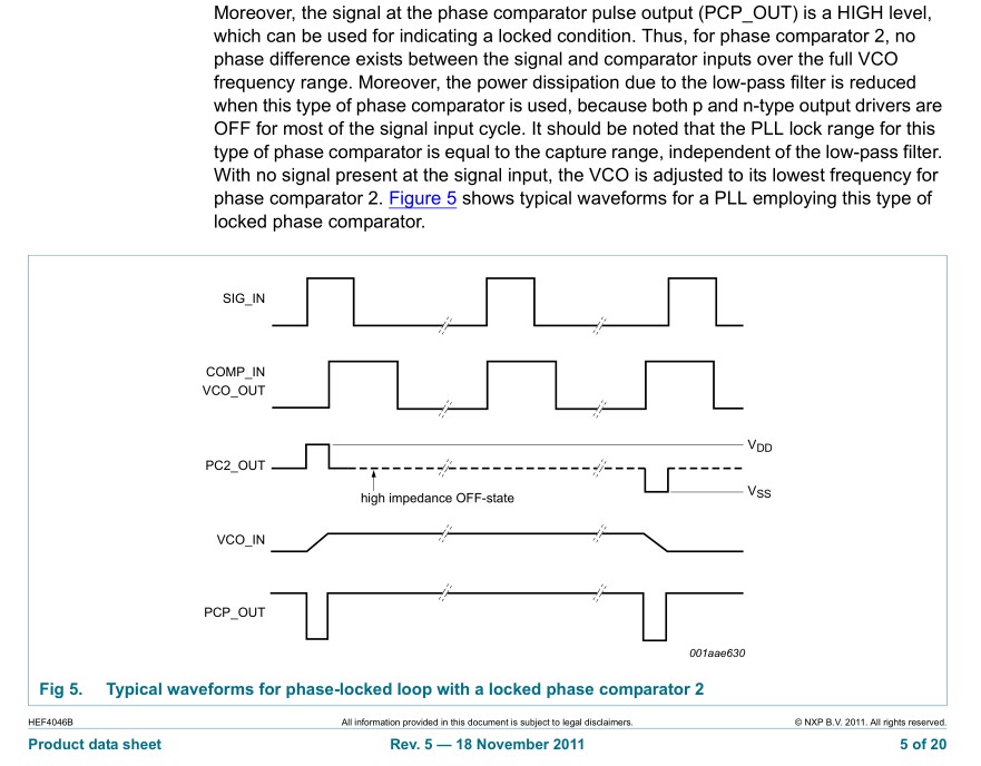
Continue to Site

Welcome to EDAboard.com

Welcome to our site! EDAboard.com is an international Electronics Discussion Forum focused on EDA software, circuits, schematics, books, theory, papers, asic, pld, 8051, DSP, Network, RF, Analog Design, PCB, Service Manuals... and a whole lot more! To participate you need to register. Registration is free. Click here to register now.

is this synthesizable

Status
Not open for further replies.

hulk789

Junior Member level 3
Joined
Jul 18, 2015
Messages
27
Helped
0
Reputation
0
Reaction score
0
Trophy points
1
Activity points
211
is this code synthesizable
Code:
always @ (posedge clk, negedge clk) begin
....
end

and

@ (posedge clk)
OUT=1;

and 

always @ (in1,in2) begin
....
end
 

Better you start with your opinion, why do you think this code is might not synthesize?
 

Better you start with your opinion, why do you think this code is might not synthesize?
A flip flop cannot be triggered at both the positive edge and negative edge
 

I think the focus should be regarding the target implementation type - FPGA or ASIC.

I know it will not be syth for FPGAs, as FPGAs do not have flip-flops that can trigger on both edges of a clock.

But for ASICs I think design syth. could be possible. e.g. - We know that DDR memories work on both clock-edges.
 

I know it will not be syth for FPGAs, as FPGAs do not have flip-flops that can trigger on both edges of a clock.

But for ASICs I think design syth. could be possible. e.g. - We know that DDR memories work on both clock-edges.

Provided you have a hardware that has dual edge clocking, I doubt that
Code:
always @ (posedge clk, negedge clk)
is a legal hardware description. According to IEEE Std. 1800-2012, a dual edge sensitive event should be described:
Code:
always @ (edge clk)
 

what about
Code:
@ (posedge clk) 
OUT=1;
waits for the positive edge and assigns the value
 

It's of course synthesizable. If you don't specify OUT to be initialized to 0 (e.g. by initial block or general synthesis constraints), the statement might be synthesized as constant 1.
 

It's of course synthesizable. If you don't specify OUT to be initialized to 0 (e.g. by initial block or general synthesis constraints), the statement might be synthesized as constant 1.
It's not synthesizable standalone in a module unless it's inside a procedural statement, i.e. always or initial.

Not synthesizable:

Code Verilog - [expand]
1
2
3
4
5
6
7
8
9
10
module test (
  output reg q,
  input d,
  input clk
);
 
@(posedge clk);  // this line reports an error on the @
q = d;
 
endmodule


Both are synthesizable:

Code Verilog - [expand]
1
2
3
4
5
6
7
8
9
10
11
12
13
14
15
16
17
18
19
20
21
22
23
24
25
// using initial statement:
module test1 (
  output reg q,
  input d,
  input clk
);
initial begin
  forever begin
    @(posedge clk);
    q = d;
  end
end
endmodule
 
// using always statement:
module test2 (
  output reg q,
  input d,
  input clk
);
always @* begin
  @(posedge clk);
  q = d;
end
endmodule


But why would you go to all the trouble of abusing Verilog synthesis when the standard template for a FF is simpler then either of these methods?

Code Verilog - [expand]
1
2
3
4
5
6
7
8
9
10
11
module test2 (
  output reg q,
  input d,
  input clk
);
always @(posedge clk) begin
  q <= d;
end
// optionally the one liner:
// always @(posedge clk) q <= d;
endmodule


I only use the @(posedge clk) in tasks and initial blocks, which get used in my testbenches.
 

Code:
always @ (posedge clk1) begin
    @ (posedge clk2)
    OUT=1;
end
I mean if this is synthesizable
 

This is definitely not synthesisable. Your code describes logic that is trying to detect a clock edge that is exactly CO incident with another clock edge, which is impossible.
 

Code:
always @ (posedge clk1) begin
    @ (posedge clk2)
    OUT=1;
end
I mean if this is synthesizable

Arrrggghhhh! Read your original question, you did not ask this question!
 

This requirement is actually similar to the Type II phase comparator in the old CD4046B PLL except it goes high when one leads the other and low when it lags then becomes tri-state floating when in sync.

The output pulse width is thus a current pulse that can be integrated with a cap load to measure the phase error and for this mixer the PLL is in sync with coherent rising edges and the Vout integrates to what is required to keep the VCO at the same frequency and phase lock.

Thus this Type II mixer is called a Phase/Frequency detector.

3759963200_1438018302.jpg


The timing diagram of logic states appears below.
3776615700_1438018303.jpg


To realize this in code the CPU cycle counts must be tiny compared to the input clocks being compared to avoid the dead-time ambiguity.

Similarly in hardware , the dead-time is limited by the signal propagation latency.
 

Status
Not open for further replies.

Part and Inventory Search

Welcome to EDABoard.com

Sponsor

Back
Top