jabbar81
Newbie level 4
- Joined
- Mar 27, 2006
- Messages
- 7
- Helped
- 0
- Reputation
- 0
- Reaction score
- 0
- Trophy points
- 1,281
- Location
- Seoul, Korea
- Activity points
- 1,371
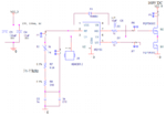
I am making a Piezoelectric actuator driving circuit using Half Bridge. I have to make it work at 220Vrms, 60Hz line voltage. Currently I am testing it at 100Vrms, 60Hz voltage. The line voltage is rectified and converted to DC link Voltage. IR2153S is used as driving chip to drive piezoelectric actuator at 74kHz, using square output wave.
I am getting burning MOSFETs and IR2153 above 100Vrms main input.
The oscilloscope screenshot of PCB is attached.
Blue-Channel-1: is the Hi-side MOSFET Gate Voltage w.r.t GND
Green-Channel-2: is the Lo-side MOSFET Gate Voltage w.r.t GND
Purple-Channel-3: is the input voltage to Piezoelectric Actuator.(input capacitance of Piezoelectric 0.3nF)
Green-Channel-4: is the input current to Piezoelectric Actuator.
Problems
(point-1): I have dead time when Hi-side MOSFET is getting On.
(Point-2): No dead time, when Hi-side MOSFET is turning OFF, though I can see little transition in voltage when hi-side MOSFET should turn off.
(point-3): High output current pulses/spikes at switches ON/OFF, I think they are responsible for damaging the switches.
(Point-4): ringing in the Lo-side MOSFET gate voltage.
Without load, the dead-time of the gate voltage is correct.
How I can solve the no dead time, current spikes and ringing issues. Any suggestion?
I tried some sunbber circuit, diode in parallel with gate resistors, changing C6, 22-ohm R5, but couldn't solve the any problem specially dead-time problem.