abcd567
Newbie level 6
WIRE COLLINEAR
I have noted some contradiction in coil dimensions in this drawing of wire collinear by G-7RGQ.
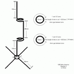
It says the coil consists of 1½ turns of 10 mm dia. The length of wire in coil therefore works out to π x d x 1.5 = 3.14 x 10 x 1.5 = 47mm. Adding 4 mm wire to provide gap between turns, the total wire length becomes 51 mm. However the drawing mentions "total wire length in coil = 65.5 mm (¼ wavelength)".
SIMULATIONS
I have run 2 simulations of wire collinear by G-7RGQ:
Simulation 1: Using 10 mm dia, 1½ turns coil, as given in drawing.
Simulation 2: Using 14 mm dia, 1½ turns coil, calculated by wire length in coil = 66 mm, i.e. ¼ λ.
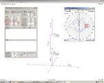
The simulation results show a marked improvement in Radiation Pattern as well as in Horizontal Gain when 14 mm dia coil (i.e. wire length = 66 mm) is used. SWR in both cases are more or less same and substantially high (i.e. SWR > 6)
10 mm dia coil
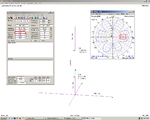
14 mm dia coil
NOTE:
Diameter of the coils in simulations is measured from center of the wire.
Hence the inner dia of coil (i.e. the dia of rod or drill bit on which the coil is wound) = dia of coil - dia of wire.
If a 2 mm dia wire is used:
The 14 mm dia coil should be wound over a rod/drill bit of dia = 14 mm - 2mm = 12 mm
The 10 mm dia coil should be wound over a rod/drill bit of dia = 10 mm - 2mm = 8 mm
AN EASIER WAY to make the coil accurately is to measure & cut 66 mm length of wire and then wind it over a rod or drill bit. In this case exact dia & number of turns is not important as the wire length is pre-cut to 66 mm (i.e. ¼ λ). A 1/2" (12.5 mm) or 3/8" (9.5mm) drill bit can be used to wind the coil. The coils and vertical sections can then be joined by soldering/brazing/welding
I have noted some contradiction in coil dimensions in this drawing of wire collinear by G-7RGQ.

It says the coil consists of 1½ turns of 10 mm dia. The length of wire in coil therefore works out to π x d x 1.5 = 3.14 x 10 x 1.5 = 47mm. Adding 4 mm wire to provide gap between turns, the total wire length becomes 51 mm. However the drawing mentions "total wire length in coil = 65.5 mm (¼ wavelength)".
SIMULATIONS
I have run 2 simulations of wire collinear by G-7RGQ:
Simulation 1: Using 10 mm dia, 1½ turns coil, as given in drawing.
Simulation 2: Using 14 mm dia, 1½ turns coil, calculated by wire length in coil = 66 mm, i.e. ¼ λ.
The simulation results show a marked improvement in Radiation Pattern as well as in Horizontal Gain when 14 mm dia coil (i.e. wire length = 66 mm) is used. SWR in both cases are more or less same and substantially high (i.e. SWR > 6)
10 mm dia coil

14 mm dia coil

NOTE:
Diameter of the coils in simulations is measured from center of the wire.
Hence the inner dia of coil (i.e. the dia of rod or drill bit on which the coil is wound) = dia of coil - dia of wire.
If a 2 mm dia wire is used:
The 14 mm dia coil should be wound over a rod/drill bit of dia = 14 mm - 2mm = 12 mm
The 10 mm dia coil should be wound over a rod/drill bit of dia = 10 mm - 2mm = 8 mm
AN EASIER WAY to make the coil accurately is to measure & cut 66 mm length of wire and then wind it over a rod or drill bit. In this case exact dia & number of turns is not important as the wire length is pre-cut to 66 mm (i.e. ¼ λ). A 1/2" (12.5 mm) or 3/8" (9.5mm) drill bit can be used to wind the coil. The coils and vertical sections can then be joined by soldering/brazing/welding
