Continue to Site

Welcome to EDAboard.com

Welcome to our site! EDAboard.com is an international Electronics Discussion Forum focused on EDA software, circuits, schematics, books, theory, papers, asic, pld, 8051, DSP, Network, RF, Analog Design, PCB, Service Manuals... and a whole lot more! To participate you need to register. Registration is free. Click here to register now.

Really Advanced LED Circuit Design for a DC Model Train

Status
Not open for further replies.

Sopetard666

Newbie level 3
Joined
Jul 3, 2015
Messages
3
Helped
0
Reputation
0
Reaction score
0
Trophy points
1
Activity points
34
I need help with a circuit I haven't been able to find one like it

so any way I'll have to describe it

I'm trying to wire a model train so
when it reverses it has a led to light the way
but when I add a auxiliary tender it is block
so I'm trying to add a led to the aux tender
but I don't want the first led on when the second one is
I also have a second aux tender I use too
so I also don't want the first two LED's on when the third one is


Does anyone know how to wire this circuit or make a circuit diagram like this?
 

So you want a circuit where only the light at the back works and any others are turned off, regardless of how many tender there are?

Brian.
 

How will the led get power? Every tender will have exclusive battery?
If power comes from the first one, then you could use jack 2,5mm monophone male-female connectors on front-back of the tender.
The female connector have 3 pins, the 2 are shorted together except if a female jack is entered.
So if pins are shorted, power will light the led on this tender, othherwise it will send power to the next tender.

If every tender is self powered you will need a cheap solution (eg a simple jumper or micro switch) or a reed switch (in the back of every tender) and a magnet (in the front of every tender).
 

How will you wire up the cars to detect they are connected?

Do you have DCC? or analog power on the tracks with polarity reversal?

A priority encoder is easy when all inputs are handy. You don't have any inputs yet.
How about magnet coupling sensor (Hall and magnet) when paired?

This idea is a bit thin to realize without more physical details on sensing and intercar connections needed.
 

The way I'm powering the aux tenders is I'm going to buy small magnets and soldier flexible wire to them and make them look and act like glad hands (air brake lines).
The model is DCC the tenders are brass (has no decoder) the locomotive is non-brass (has a sound decoder).
And yes Betwixt has the right idea of what I'm trying to make.
 

I still have a problem with the supply for the LEDs. Ignoring that,brake lines come in pairs? so use one as the LED supply with the rail/rails being the common. Use the other brake line as a common for daisy chain switching the LEDs and have a transistor driving each LED in each car with its base normally fed via a resistor so the LED is on. Plugging in the next car feeds a short backwards so turning that LED off.
Frank
 

Assuming the train has an electrical supply from the tracks or an internal battery, all you need is a reed switch at the rear of each tender and a magnet at the front of each tender. The reed switch turns the LED on if there is no magnet close by, in other words the tender without one following it. No need to check any other part of the train, it's just a switch, resistor and LED in each tender, all working independently.

If it has to work the same with the train running backwards (in reverse) I would assume power comes from the tracks so some diodes to steer the current might also be needed.

Brian.
 

Um I was trying to say the tenders are being powered from the locomotive, then using two 3mm x 3mm x 3mm magnets with flexible wire attached on each side of the tender because a magnet is metal it can hold a current. Then the wire would power the led because it would be in the circuit with the reverse led in the main locomotive tender. The LEDs would be wired in a parallel circuit but I need help trying to find a way to make the LEDs turn off when the next led is added in the Circuit meaning that the last led is on but the ones before it are off.
Hopefully that this will clarify things!
 

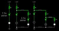
Here is a simple method. Add zener diodes inline with the first two led's. Add resistors to limit current through the led's, as necessary.

Select zener and resistor values, so that adding a tender creates the correct voltage drops.


The bright whites are typical 3.6 V.

No led is exposed to more than 17 mA.

The above is the best I could achieve, with a 12V supply. You'll have to do some experimenting if your supply V is different.
 
Can you use a mini plug/ jack?
one at front, one at back?
If plug is inserted in front and not in back,
LED on
if plug is inserted in front and back
LED off
 

Can you use a mini plug/ jack?
one at front, one at back?
If plug is inserted in front and not in back,
LED on
if plug is inserted in front and back
LED off

If you are talking about my schematic, then Yes, you can use plugs and jacks. (Notice my schematic has disjointed lines connecting each stage. That represents any kind of switch or connector that you wish.)

There are jacks which contain a switch, to turn off the preceding stage automatically when you insert a plug. (The plug can be ordinary 2-conductor). These jacks are the kind you'd use to switch off the loudspeaker when you plug in an earphone.

You can adapt such jacks to your lighting system, and do without any fancy circuitry.

hi

No...the question was intended for the OP.
 

If you are talking about my schematic, then Yes, you can use plugs and jacks. (Notice my schematic has disjointed lines connecting each stage. That represents any kind of switch or connector that you wish.)

There are jacks which contain a switch, to turn off the preceding stage automatically when you insert a plug. (The plug can be ordinary 2-conductor). These jacks are the kind you'd use to switch off the loudspeaker when you plug in an earphone.

You can adapt such jacks to your lighting system, and do without any fancy circuitry.

Regarding your schematic...if you use pugs and jacks you don't need zeners...
 

Status
Not open for further replies.

Part and Inventory Search

Welcome to EDABoard.com

Sponsor

Back
Top