Continue to Site

Welcome to EDAboard.com

Welcome to our site! EDAboard.com is an international Electronics Discussion Forum focused on EDA software, circuits, schematics, books, theory, papers, asic, pld, 8051, DSP, Network, RF, Analog Design, PCB, Service Manuals... and a whole lot more! To participate you need to register. Registration is free. Click here to register now.

[SOLVED] Temperature cut off?

Status
Not open for further replies.

Englewood

Full Member level 3
Joined
Nov 2, 2014
Messages
178
Helped
0
Reputation
0
Reaction score
0
Trophy points
16
Activity points
1,294
Hello,

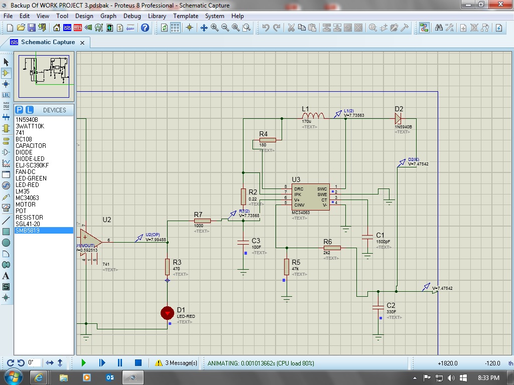
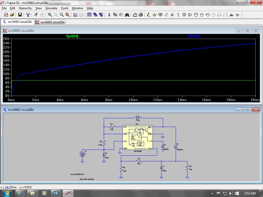
I want to design a circuit so that when a temperature of say 100C is reached i get a 24v output to triger a safety cut off.

Is this possible using a LM35?
 

Yes, a LM 35 and a comparator can work. There are bimetal switches set to 100 deg.C that can also switch a high current quite reiably. No electronics ad no power needed.
 

Hi, in principle yes it should. 100ºC is 1V output for the LM35 (correct me if I'm wrong).

I think you need something other than a 741 to get the 24V output you need, unless you use it to drive a transistor; I think the 741 only goes to 14V output.

What you suggest looks similar to a circuit used to control a fan. If you want to see the fan idea explained well, look for: "THE HEATSINK GUIDE: Build yourself a fan temperature control" at this link:

http://www.heatsink-guide.com/peltier.htm

The temperature controlled fan link is "hidden" in the side menu on the left-hand side of the page with the title "Temperature control"

I'd thought about adapting the fan controller and making it with an LM35 instead of the NTC sensor, your circuit link looks good too.

Another way is using something like a 3914 or a 3915 and getting it to trigger on one of the outputs that represents 100ºC, but you'd still need a "power" driver to get the 24V, and your way is easier/less parts.

Yes i think i would use a transistor to output 24V, thank you for the information its useful :)
 

I use LTsplice software for a test build, is there a LM35 in the software cant seem to find one :-(
 
Last edited:

Hi there! I just looked at LTs products and did a couple of other web searches, and in principle there doesn't appear to be a pin-for-pin LM35 type device in their products for temp. sensors, maybe I missed it (but I doubt that), they have other types of temp. sensor. If it, or a similar device, is not in the components bin in the program, probably not.

I found this thread from another web (dated 2005), may not help much:

https://www.electronicspoint.com/threads/searching-for-spice-model-national-lm35.43595/

Tina-TI... I was unable to exe. the file, no idea why(boo hoo!) as it wasn't an exe. format, but the TI "Tina-TI" is a Spice program that looked really useful, especially if you use their devices. It only takes a few mins. to register and they were fast about accepting a user request to download the program installer. Maybe you could use it as a complement to LTSpice.

I think you can model some of your own devices on LTSpice, but it looked very hard to do as you need to know a lot of parameters.

I imagine you are using devices that are not convenient to breadboard or you have a specific goal that breadboarding cannot fulfil.

Good luck, hope you found a suitable drop-in part.
 

I'm pretty sure you'd be money ahead, using a Selco thermostat
from Digi-Key. They come in 5C to 10C increments, relatively
compact (about the scale of a TO-220 although not a transistor
form factor), durable and don't care if you want to run them off
1V or 100V. Plus, not the least bit needy of housekeeping supplies
or post-processing to get the bang-bang job done. You could
conceive of ways to fail and go into thermal overload, that take
out one of the analog circuitry's supplies and defeat your warning
or cooling outcome, I expect.

Particularly when it comes to protection functions, independence
and simplicity are very good things.
 
  • Like
Reactions: d123

    d123

    Points: 2
    Helpful Answer Positive Rating
Thanks for the information
Proteus 8 come the the rescue, its awesome :)


Okay,

I have made my circuit but im not getting an output voltage of 24v from the IC.

Can anyone suggest what i neeed to do.

I have made the LED come on at 59C and the voltage increses from 1.5v to 8v from the opamp.

I get a 8v output from the op-amp and the goes to the input of the boost converter but in getting 0.2 v out of the boost converter :-(.
 

It looks to me like you're trying to make the 741 op amp be
the power supply for your boost converter. Are you sure,
really sure, that the op amp likes that plan? Most are
not real big on sourcing current, and the startup phase
might never even take off if you can't get past the input
undervoltage lockout on the boost converter part. The
input current draw can have "humps" which need a decently
low input impedance to get over, and a current-limited
output might fail at this. Like roller skating uphill.

Suggest you cut this apart and power pieces separately
with supplies you can know and trust, and look for clues
on your own bench (or e-bench).

And don't bet on freebie macromodels doing a complete
job of secondary features, like details of op amp output
current limiting and boost converter startup current
profile - the latter particularly is very much about circuit
design details, internal. And varies plenty with PVT, so
even if you get a happy answer, such a chain of dependencies
stands a good (bad) chance of failing later when somebody
looks at it closer and throws outlier samples into the mix.
 

Very helpful reply.

Can i take the supply for the boost converter from the 9V supply for the LM35 circuit?

I dont want 2 seperate suplies.
 

Hi, if the boost converter works off 9V you can with no problems.
The power supply is the dispenser to draw the heavy duty juice from, whereas the devices talk to each other with the signals, it's not the same thing; the power supply is an abundant reservoir, the signals are a little stream.
If DRC and/or IPK are like enable pins or a logic (high/low) input signal they get the 741 signal, the boost converter gets it's output power from the supply rail (v+).

- - - Updated - - -

Hi again!

I don't know boost converters, so I assume that they can be powered by a lower rail supply than they can create on the output, so you'll know if with 9V going into V+ it can create a 24V output.

More importantly, perhaps, If I have it right, according to the calculation on page 11 of the OnSemi datasheet it says: Vout = 1.25 * (1 + R2/R1).

Check you haven't got R1 and R2 reversed on just your schematic or possibly in your real circuit, you might be creating 1.3V output instead of the 22.6V the calculator tells me you'll get with R2 as 2K2 and R1 47K.
If you make R1 50K you'll get a hypothetical 23.97V output.

https://www.onsemi.com/pub_link/Collateral/MC34063A-D.PDF

Good luck, that's a nice circuit.
 

Hello,

Iave had a little play around with R1/R2 and i can get the voltage to change but i can only seem to get an out put of 7.6V from the boost with 7.7V going in :-s

Thanks for the help.
 

I think the software doesnt like the MC34063 it doesnt seem to show a boost for some strange reason :-S
 
Last edited:

Hi there!

What's a boodt? I like real prototyping, real-time depressing failures I can't understand before my eyes! ...Until the devices become so small I have to simulate everything

I don't know what pin 6 is supposed to do as it says V+ in your schematic, and Vcc in the datasheet I saw. Sorry to ask a stupid question, but are you sure this device should be powered by the OpAmp? Vcc and V+ tend to mean the positive rail.

The 741 looks like it's sending a signal, not providing the power to the device. A few months ago I tried to power a 555 V+ pin from another 555s output pin, and the results were not good - a very low voltage output from 555 #2, insufficient to output more than 4 volts (the supply rail was 9V powering the first 555, whose output was about 7V). Usually any device needs it's own lifeline to the supply rail in order to function correctly. My car needs new petrol, not used petrol to work. ;)

Don't know if the OnSemi Application Notes mentioned in that datasheet could help: AN920A/D and AN954/D

Maybe it's worth trying the 34063 pin 6 connected to the positive rail, and figuring out which of the other pins is the signal input/the "enable" pin, which should be turned on by the 741 output in your circuit.

If you look at other datasheets for the same device, usually one or two have fairly complete schematics that help to understand what to do with the device better. Guessing, you could try the datasheets by TI, or NXP, or Linear Technology for the "typical applications" section.

The sparse schematic for a step-up converter on page 5 of that datasheet says 12V in to pin 6 = 28V out. If the issue has nothing to do with pin 6 input from the positive rail, you could try adding a BJT or do it the lazy way I like and use a MOSFET (as they are only interested in voltage, not current to be turned on) after the 741 to boost the input signal; the 741 output into an NPN into a PNP or into an NMOS into a PMOS into the 34063 could help; it's two components and two resistors more, but as some circuits always seem to need "Just one more component and it'll work", might be worth a try. Remember pin 6.

Have fun!
 

I meant a boost of Voltage.

I have tried putting a 9V supply to pin 6 and the voltage output stays the same, nothing changed.

I have tried running the op-amp to different pins to find the trigger pin but nothing changed again.

I think i might try the approach of two Transistors to boost the volatge as the less components the better.

I simulated the MC34063 with LTsplice and it work fine with a volatge in of 7V and a volatge out of 24V.

Maybe its the proteus software
 

Hi!

You "boodt" voltage, I "liminted" current in another thread! Are you only simulating this? If LTsplice gave a positive result (24V), if they're not expensive, why not test/waste components on a real or a rough version protoboard to see what happens?

Maybe you're right and the simulation software isn't simulating what happens on a real board. I'm a caveman, I still use PDIP mainly, and I prefer to do things on a breadboard/half-made PCB + breadboard as simulating seemed to be hit and miss in my limited experience and can give incorrect results, or say that a circuit won't work but it will in reality, especially if you omit important device parameters or can't simulate the whole circuit due to no temp sensor in program A and no something else in simulation program B.

The transistors between the 741 and the 34063 are at least worth trying.

Hope it works soon.

- - - Updated - - -

Hi again! I was looking at the TI datasheet for a boost converter application, "Step-Up Converter Application" on page 13, and looking at the schematic you posted for what I imagine is the Proteus simulation, it looks like the 5819 Zener diode could be the wrong way round, and the 180K resistor goes into pin 8, not to the inductor, is this possible? Your LTsplice schematic looks correct. If so, I'd try that before adding any transistors.

The TI datasheet and application note are here:

MC3x063A 1.5-A Peak Boost/Buck/Inverting Switching Regulators

https://www.ti.com/lit/ds/symlink/mc34063a.pdf

and here:

Application of the MC34063 Switching Regulator

https://www.ti.com/lit/an/slva252b/slva252b.pdf

Good luck!
 
Last edited:

Im only simulating this circuit.

I could test on breadboard with components but i wanted to simulate first, as this is my first circuit design.

Proteus doesnt have a 5819 zener so i used a equilivant version.

I assume the 180 resistor is linked to pin 8 and the inductor.

Im sure its the software thats at fault.

I think im going to change my design so that there is a contant 24V flowing through the LM35 and when the temp hits 60C the 24V cuts off to 0V.

Somehow
 
Last edited:

Cap values were entered incorrect.. Always Double check.. uF not F
Op Amps are not intended to drive inductive boost regulators.

For this we use CMOS diode voltage doubler strings with charge pump boost design. See same name in IC's
 

Status
Not open for further replies.

Part and Inventory Search

Welcome to EDABoard.com

Sponsor

Back
Top