Continue to Site

Welcome to EDAboard.com

Welcome to our site! EDAboard.com is an international Electronics Discussion Forum focused on EDA software, circuits, schematics, books, theory, papers, asic, pld, 8051, DSP, Network, RF, Analog Design, PCB, Service Manuals... and a whole lot more! To participate you need to register. Registration is free. Click here to register now.

Feed Probes in Coaxial and Rectangular Waveguides - wider band?

Status
Not open for further replies.

Darktrax

Full Member level 5
Joined
Nov 28, 2009
Messages
287
Helped
103
Reputation
206
Reaction score
100
Trophy points
1,323
Location
UK
Activity points
5,268
Cable-fed probes inserted into a wavguide space are familiar to many. They generally insert about half way into the shorter space, and can be variously given cylinder or conical end shapes. Even the centre conductor of a coax cable inserted like this can give 10dB RLR.

Things get more awkward when trying to launch into the gap of a coaxial waveguide (these are often parts of multi-band feed-horns), so one has to use a pair of opposite probes fed in 180° phase, but the probes look the same.

I have tried so many now. There are times when one can get very good return loss, meaning 18dB or 20dB, or even up to 30dB, but only over very narrow bandwidths such as 1% or 2%. For "bandwidth", I mean anything better than (say) 15dB RLR. Even 12dB would be OK provided it was at least that at the band edges.

Are there any ways of doing this so as to get a sightly wider bandwidth - say maybe 6%?

I am not familiar with " coaxial waveguide probes". The waveguide-to-coaxial transitions are typically covering the full waveguide bandwidth with RL>16 dB. There are several designs, kept under makers' "know-how". Look in some to learn how it is done. This look will also show you why they are quite expensive.
Stepped-diameter design expands transition bandwidth in most such designs. Stepped transformers, too.
 

I would look at a double ridge to waveguide transition. the coax probe attaches to the ridge. can get multi-octave bandwidth
 

Thanks for repies Jiripolivka and biff44

Re: Coaxial waveguides. These can look like a (usually short) version of a coaxial cable structure, but are very different in operation.
coaxial-radial-field.png
The difference is that in a coaxial (cable-type) structure, the centre part is not connected to the outside, but is directly driven with alternating voltages. The electric field is radial everywhere, and has magnetic components at right angles to the electric field, which makes them circular. The energy propagates at right angles to both, down the cable in a special mode TEM. If it reaches the end without finding a termination, it will return, messing up the fields travelling the other way into standing wave patterns.

**broken link removed**

A coaxial waveguide is like a regular circular waveguide with a conducting bit up the middle which is at the same potential as the outer, ie. "grounded". The next picture shows a proper TE11 and a TE21 mode field pattern. If a launcher probe was inserted at (say) the top side, it would generate a local field similar to a piece of the radial-type TEM sort. The way to "force" a proper TE11 wave is to use four probes, with those diametrically opposite each other being fed 180° out of phase. This is common in feed schemes where there is enough frequency separation that the small waveguide can be placed up the middle of the large lower frequency waveguide in some multi-band feeds.

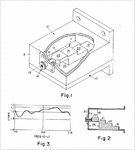
The problem is how to get a short probe or launcher to work in the gap space, hence the original question. There are a variety of schemes, including taper fins, and stepped fins, and the stepped transformer from 1973 shown in the next picture. If the horizontal lengths of the steps are anything near quarter-wave, the whole business will get very long at the lower microwave frequencies. Trying to get this type of launcher to work in the gap was not exactly showered with success!
**broken link removed**

Biff44's suggestion of feeding a ridge wavguide is interesting, possibly similar to the taper-fin and stepped fin types I have seen. Given that in the usual way, by the time I post a question, I have already heavily trawled for answers, we do not expect any easy answers unless someone gets lucky. Launching a modest bandwidth with nominally OK return loss into this space is not easy!
 
Last edited:

I can only see the first picture showing the typical TEM field pattern in coaxial waveguide. As you mention that feeding posts should be fed with 180-deg phase difference, this sounds like a resonant structure, not too wideband. Using fin-line approach offers a wider bandwidth but launching specific modes often requires structures that reject other unwanted modes.

I would check older books where various modes were studied, like Harvey, Microwave engineering, ~1960. Maybe a solution to your problem exists.
 

Hi jiripolivka

Hmm - I am so sorry about the pictures. I don't know what happened there.
I shall try again. The words assume pictures are available, and can get meaningless without them.

The field patterns should show a TE11 and a TE21 mode in a coaxial waveguide. This takes a little mental note when it comes to comparing with rectangular waveguides. A TE11, as needed for circular polarization, could only happen in a rectangular waveguide where the shorter dimension was still large enough to fit the wave, which is why TE11 usually ends up using a square waveguide. When we have a coaxial waveguide, there is no distinction about where the "corners" would be. The field shown looks like a TE10, but the waveguide can simultaneously support another one at right angles to the first.

coaxial-waveguide-fields.png
stepped-transformer-launch.png
I had thought of using a stepped transformer in place of every regular probe. This would make two fed in 180° opposition for a linear polarized wave.

To get circular polarized wave would require four probes (as two pairs each fed in opposition) , but with one pair set a 90° to the other, and that one pair further delayed by 90°.

I thank you for your suggestion of a fin-line launch, and I will be exploring these. As you mentioned, available specific design information for nearly all forms of wide(er) band matched launchers is somewhat limited, even for stuff that has been there for decades.
 

Status
Not open for further replies.

Part and Inventory Search

Welcome to EDABoard.com

Sponsor

Back
Top