Welcome to our site! EDAboard.com is an international Electronics Discussion Forum focused on EDA software, circuits, schematics, books, theory, papers, asic, pld, 8051, DSP, Network, RF, Analog Design, PCB, Service Manuals... and a whole lot more! To participate you need to register. Registration is free. Click here to register now.
can i get a circuit of a bjt L-C oscillator which can actually be implemented on hardware? I tried many circuits from internet of hhartley oscillator but none of them was working.
can i get a circuit of a bjt L-C oscillator which can actually be implemented on hardware? I tried many circuits from internet of hhartley oscillator but none of them was working.
can i get a circuit of a bjt L-C oscillator which can actually be implemented on hardware? I tried many circuits from internet of hhartley oscillator but none of them was working.
Do you know the working principle of the Hartley oscillator or some other (similar) LC oscillators?
Or did you just copy a design that was found elesewhere?
More than that, do you have any idea about the endavoured oscillation frequency?
can i get a circuit of a bjt L-C oscillator which can actually be implemented on hardware? I tried many circuits from internet of hhartley oscillator but none of them was working.
The 2nd stage is used as a linear unity gain Amp that can drive 200 Ohms with low distortion but when load drops in Resistance it reaches 50% when it matches the 2x ESR of the CMOS output. Both stages use negative feedback for self biasing and the internal ESD protection with Schottky diodes clamps the high Q gain in the feedback loop, where the C-L-C network gives the stable 180 deg . phase shift at resonance.
The output power into 50 Ohms is around 10dBm at 83 MHz. Scale L & C values only to adjust f. Notice this circuit is identical to a crystal oscillator except the internal LC values of the crystal internally give a Q that is 100x bigger. (>10k)
Press switch to connect load (Simulation link in 1st line) and allow time for coupling cap to charge up.
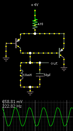
Right, if we try to make the LC oscillate with just one transistor then what you describe will happen. More components need to be added.
The long-tail pair is configured for trigger action. One transistor turns the other off.
The left-right switching action can be made very sensitive. Notice there are no resistors on the bias wires. The transistors are at maximum gain. Overall current flow is kept to a reasonable amount by the emitter resistor.
This site uses cookies to help personalise content, tailor your experience and to keep you logged in if you register.
By continuing to use this site, you are consenting to our use of cookies.