nalawade
Junior Member level 2
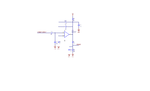
The input to the non-inverting terminal is voltage signal across a resistor. The resistor is connected between IGBT emitter and ground.
Thus the input is a voltage signal taken across that resistor. The frequency of the current is close to 25 kHZ.
The signal is applied to an opamp with gain of 100.
I wan to know how the designer has selected all the components used for designing the opamp circuit.
I am not concerned with the voltgae divider circuit at the output of the opamp, I just want to know the designing of opamp. Why the feed back capacitor, why the input RC filter. Why the pull up resistor and capacitor in parallel to pull up resistor.
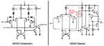
Note opamp is designed using LM339 AN by fair child
Thus the input is a voltage signal taken across that resistor. The frequency of the current is close to 25 kHZ.
The signal is applied to an opamp with gain of 100.
I wan to know how the designer has selected all the components used for designing the opamp circuit.
I am not concerned with the voltgae divider circuit at the output of the opamp, I just want to know the designing of opamp. Why the feed back capacitor, why the input RC filter. Why the pull up resistor and capacitor in parallel to pull up resistor.
Note opamp is designed using LM339 AN by fair child