thranduil
Member level 1
Hi all gus,
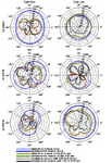
I am dealing with radiation pattern of TPMS sensor. Unfortunatelly I am not able to visualize it in 3D and to realize consequences. On the diagram one can find both measured and simulated radiation patterns for standalone sensor, sensor attached to the wheel only and sensor attached to the wheel with tire. Here is the diagram:

What I would say is that in hor. plane, antenna radiation pattern (blue line) is similar to dipole, while in ver. pol. plane it approoximates isotropic radiator.
Since this transmitter is constantly rotating, what would be the optimal reception antenna design?
What can I actually have from information on both hor. and ver. pol. plane? Should I use both ver. and hor polarized antennas?
Many thanks
I am dealing with radiation pattern of TPMS sensor. Unfortunatelly I am not able to visualize it in 3D and to realize consequences. On the diagram one can find both measured and simulated radiation patterns for standalone sensor, sensor attached to the wheel only and sensor attached to the wheel with tire. Here is the diagram:

What I would say is that in hor. plane, antenna radiation pattern (blue line) is similar to dipole, while in ver. pol. plane it approoximates isotropic radiator.
Since this transmitter is constantly rotating, what would be the optimal reception antenna design?
What can I actually have from information on both hor. and ver. pol. plane? Should I use both ver. and hor polarized antennas?
Many thanks