Continue to Site

Welcome to EDAboard.com

Welcome to our site! EDAboard.com is an international Electronics Discussion Forum focused on EDA software, circuits, schematics, books, theory, papers, asic, pld, 8051, DSP, Network, RF, Analog Design, PCB, Service Manuals... and a whole lot more! To participate you need to register. Registration is free. Click here to register now.

[SOLVED] Pic18 Interfacing with LM35DZ

Status
Not open for further replies.

Praveen Kumar P S

Member level 4
Joined
Aug 21, 2014
Messages
79
Helped
1
Reputation
2
Reaction score
1
Trophy points
8
Location
India
Activity points
627
Hello guys....
I wanted to interface my Lm35 with pic18f4550...

here is my code::
Code:
#include <18f4550.h>
#device ADC=10
#fuses XT, HS, NOWDT, NOPROTECT, BROWNOUT, NOLVP, PUT 
#use delay(clock=48000000)
//#use rs232(baud=9600, xmit=PIN_C6, rcv=PIN_C7,ERRORS)
#include<flex_lcd216.c>

void main()
{
float32 T , val;
delay_ms(500);
lcd_init();
lcd_setcursor_vb(1,1);
printf(lcd_putc,"\f ");
setup_adc_ports(AN0);
setup_adc(ADC_CLOCK_INTERNAL); 
for(;;)
{
set_adc_channel(0);
delay_ms(2);
T=read_adc();
delay_ms(10);
val=T*20*(5/1023);
lcd_gotoxy(1,1);
delay_ms(10);
printf(lcd_putc,"Adc Read:%3.2f ",T);
lcd_gotoxy(1,2);
delay_ms(10);
printf(lcd_putc,"Tem Read:%3.2f \xDFC",val);
delay_ms(500);
output_toggle(PIN_D1);
delay_ms(10);
output_toggle(PIN_E1);
delay_ms(10);
}

}

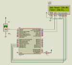
The output i got in my lcd is

Adc Read:87.00
Tem Read:0.00 C

i dont know why is it giving 0.00 ...plz help..

Thank You...
 

Please Zip and post complete CCS C project files so that the code can be compiled and tested.
 

Please Zip and post complete CCS C project files so that the code can be compiled and tested.

Thanks for the quick replay milan...
Here is my whole project:::

Thank You....
 

Attachments

  • Adc_Pic18.zip
    72.1 KB · Views: 49

Please Zip and post flex_lcd216.c file. I can't compile without that file
 

Code:
delay_ms(10);
val=T*20*(5/1023);
lcd_gotoxy(1,1);

change above lines with val= (T*5)/1000;
May solve ur problem
 

I changed the code a little and compiled for 20 MHz and it worked. If you use 48 MHz crystal or HSPLL then you need to adjust delay_cycles() in the flex_lcd216.c file. Increase the delay and it will work fine. Instead of

Code C - [expand]
1
delay_cycles() use delay_us(500).


Attachments

  • Adc_Pic18.rar
    156.6 KB · Views: 57
  • sim.png
    sim.png
    45.2 KB · Views: 72

Please Zip and post flex_lcd216.c file. I can't compile without that file

Sorry for that....

Here is my lcd driver::
Thank You...

- - - Updated - - -

I changed the code a little and compiled for 20 MHz and it worked. If you use 48 MHz crystal or HSPLL then you need to adjust delay_cycles() in the flex_lcd216.c file. Increase the delay and it will work fine. Instead of

Code C - [expand]
1
delay_cycles() use delay_us(500).


thanks for replay....
I tried to run the code with 20Mhz...but still not working..Every thing is working fine except Temp Read...it is still 0.00
Thank you..

- - - Updated - - -

Code:
delay_ms(10);
val=T*20*(5/1023);
lcd_gotoxy(1,1);

change above lines with val= (T*5)/1000;
May solve ur problem

Thanks for the replay..

I did what you have said..but still no effect....

Thank you...
 

Attachments

  • flex_lcd216.zip
    1.7 KB · Views: 51

Post your circuit.

I changed the delays in flex_lcd216.c file and it worked in Proteus 8.1. If it still doesn't work then increase the delays. I compiled for 48 MHz.
 

Attachments

  • Adc_Pic18.rar
    174 KB · Views: 50
Last edited:

hello,

What is the ref for ADC , is it 5V as +Vref and -Vref=0
so, you get 205 points for 100 °C
calculus becomes
Temp= ReadADC*100/205;

if you can use +4.096V for +VRef
you will get 250 points for 100°C
so more easy
Temp=ReadADC* 100/250;
or Temp= ReadADC *0.4;


or without floating point use:
Temp as an integer value.
Temp=ReadADc*40;
result is ! 87*40=3480
place the decimal point after the 2 first digits..
 

Attachments

  • LM335_1.jpg
    LM335_1.jpg
    57.3 KB · Views: 65

Post your circuit.

I changed the delays in flex_lcd216.c file and it worked in Proteus 8.1. If it still doesn't work then increase the delays. I compiled for 48 MHz.

Hey milan .....

Finally it worked....i give a 500ms delay after all equation part as you said...it worked...
now it shows the Temp read...but now its not showing the correect temp...

Thank You

- - - Updated - - -

hello,

What is the ref for ADC , is it 5V as +Vref and -Vref=0
so, you get 205 points for 100 °C
calculus becomes
Temp= ReadADC*100/205;

if you can use +4.096V for +VRef
you will get 250 points for 100°C
so more easy
Temp=ReadADC* 100/250;
or Temp= ReadADC *0.4;


or without floating point use:
Temp as an integer value.
Temp=ReadADc*40;
result is ! 87*40=3480
place the decimal point after the 2 first digits..

Hi paul....
I have not given any Vref...Are u saying that i should give a 5v supply to +vref pin directly....and what should be the current rating for it???

Thank You
 

No, it is internaly connected to Vdd (+5V) by default config..
Except if you want to use external +VRef ( it is RAx pin ) as a voltage reference of 4.01V

you get 87 points , is the ambiant temperature around 34°C ?
 

    V

    Points: 2
    Helpful Answer Positive Rating
Use my code. It shows the correct value for Temperature. You don't have to give 5V to Vref+ pin as you have not enabled Vref+ pin. 500 ms delay is too much. Try using 30 ms delay and see if it works.
 

Use my code. It shows the correct value for Temperature. You don't have to give 5V to Vref+ pin as you have not enabled Vref+ pin. 500 ms delay is too much. Try using 30 ms delay and see if it works.

Hey milan,
Its working with 30ms delay....but the problem is my calculation,i suppose..Lm35dz will vary by 1 deg cel/10 mV..
but i m geting adc read between 80 and 90...i.e for 85 adc value i have a temprature of 8.5 deg cel... :-?

help me plz...
Thank you..

- - - Updated - - -

No, it is internaly connected to Vdd (+5V) by default config..
Except if you want to use external +VRef ( it is RAx pin ) as a voltage reference of 4.01V

you get 87 points , is the ambiant temperature around 34°C ?

i m trying to use the internal vref...actually i didnt get what you said....i dont know how to calculate the points....
also i have this strange doubt..that i have given supply of 3.6V to Pic...so my internal Vref may be 3.6V..not 5V.correct...??

Thank You..
 

Did you try my code ? Try my code in while(1) loop.

- - - Updated - - -

Read this and configure fuses properly. https://www.mikroe.com/forum/viewtopic.php?t=10646

Try attached .hex file with a 4 MHz crystal and reply.

- - - Updated - - -

Test also this .hex file which is compiled for 20 MHz crystal.

also i have this strange doubt..that i have given supply of 3.6V to Pic...so my internal Vref may be 3.6V..not 5V.correct...??

Yes, Internal Vref+ will be VDD. If you have given 3.6V as VDD then 3.6V will represent 1023 raw adc value.

Provide 5V VDD and use below fuses and a 20 MHz Crystal.


Code C - [expand]
1
#fuses HS, PLL5, CPUDIV1, NOWDT, NOPROTECT, BROWNOUT, NOLVP, PUT, NOMCLR


Try rev1 code with 20 MHz crystal and 3.6V VDD.
 

Attachments

  • adc.rar
    3.9 KB · Views: 48
  • adc 20 MHz Crystal.rar
    3.9 KB · Views: 42
  • Adc_Pic18 rev1.rar
    174.6 KB · Views: 57
Last edited:

    V

    Points: 2
    Helpful Answer Positive Rating
hello,


but the problem is my calculation,i suppose..Lm35dz will vary by 1 deg cel/10 mV..
but i m geting adc read between 80 and 90...i.e for 85 adc value i have a temprature of 8.5 deg cel...

you are mixing points and mV.

ADC read gives points as result ..in your case, with +Vref=internal Vdd=3,6V
1023 pts for 3,6V or 3600mV
this full scale 3600mV represente 360°C or 1023 pts
so scaling is : Temp(°C)= ADC reading (Pts) *360/1023
if ADC read 85 pts => 85*360/1023=> 29.9°C
 
Last edited:

    V

    Points: 2
    Helpful Answer Positive Rating
Did you try my code ? Try my code in while(1) loop.

- - - Updated - - -

Read this and configure fuses properly. https://www.mikroe.com/forum/viewtopic.php?t=10646

Try attached .hex file with a 4 MHz crystal and reply.

- - - Updated - - -

Test also this .hex file which is compiled for 20 MHz crystal.


Yes, Internal Vref+ will be VDD. If you have given 3.6V as VDD then 3.6V will represent 1023 raw adc value.

Provide 5V VDD and use below fuses and a 20 MHz Crystal.


Code C - [expand]
1
#fuses HS, PLL5, CPUDIV1, NOWDT, NOPROTECT, BROWNOUT, NOLVP, PUT, NOMCLR


Try rev1 code with 20 MHz crystal and 3.6V VDD.

Hey milan
sorry for the late replay .
i tried your code...and it is working very well...
But i didnt understand the following code

Code:
 setup_adc_ports(AN0 | VSS_VDD)
and
Code:
 T = T / 2.84167;  //2.046;

AN0|VSS_VDD----> Is it for directly using internal Vref...
and
2.84167----->why is this used?

Thank You...

- - - Updated - - -

hello,


you are mixing points and mV.

ADC read gives points as result ..in your case, with +Vref=internal Vdd=3,6V
1023 pts for 3,6V or 3600mV
this full scale 3600mV represente 360°C or 1023 pts
so scaling is : Temp(°C)= ADC reading (Pts) *360/1023
if ADC read 85 pts => 85*360/1023=> 29.9°C

Hey paul

I understand the logic completely...
Is there any way to use the internal Vref with the help of software..i mean without specifying Vref=3.6

Thank You...
 

not possible. but you can give constant voltage in vref pin with a zener.
 

    V

    Points: 2
    Helpful Answer Positive Rating
AN0|VSS_VDD----> Is it for directly using internal Vref...

Yes, It is for using VSS and VDD as Vref- and Vref+ but it is optional. You can use just AN0. It is mentioned in your device header file.

2.84167----->why is this used?

5V = 1023 = x
1.5V = 306.9 = 150 deg C

x = 1023 * 150 / 306.9 = 500

You can use temp = adcVal * 500 / 1023


500 / 1023 = 0.4887585532746823

adcVal * 500 / 1023 can be replaced by 0.4887585532746823 or

1 / 2.046 (1/0.4887585532746823 = 2.046)


I was getting 308 instead of 306.9 as raw adc value for 150 deg C, so to adjust I used 2.84167.
 

    V

    Points: 2
    Helpful Answer Positive Rating
Hello milan....

5V = 1023 = x
1.5V = 306.9 = 150 deg C

x = 1023 * 150 / 306.9 = 500

You can use temp = adcVal * 500 / 1023


500 / 1023 = 0.4887585532746823

adcVal * 500 / 1023 can be replaced by 0.4887585532746823 or

1 / 2.046 (1/0.4887585532746823 = 2.046)


I was getting 308 instead of 306.9 as raw adc value for 150 deg C, so to adjust I used 2.84167.

I understand This clearly.........

but i didnt understand..

Code:
setup_adc_ports(AN0 | VSS_VDD);

if VSS and VDD can be used as Vref- and vref+ can we use

Temp=adc_read*100*(Vref+/1023);

Also venkadesh_M is saying that we cant use the internal Vref directly with the help of software..for that we have to use Vref pins....If it is so how to use Vref Pins?

Also i m new to ccs c compiler and pic..sorry for asking noob questions...
could u plz suggest me a good book for ccs c compiler...i have the ccs c manual...but it is not well enough...

Thank u...
 

ould u plz suggest me a good book for ccs c compiler
Embedded C Programming and the Microchip PIC by Barnett, O'Cull, Cox and of course CCS C Compiler Manual.

If you use AN) or AN0 | VSS_VDD they both are same. It will use Internal Vref- and Vref+ which is your VSS and VDD. You can use just AN0. The | VSS_VDD is optional. Default is VSS will be Vref- and VDD will be Vref+.

Just use the right equation to get temperature value from raw adc value.
 
Status
Not open for further replies.

Similar threads

Part and Inventory Search

Welcome to EDABoard.com

Sponsor

Back
Top